

Anchoring system and snap-fit methodology for erosion resistant linings
- Summary
- Abstract
- Description
- Claims
- Application Information
AI Technical Summary
Benefits of technology
Problems solved by technology
Method used
Image

Examples
first embodiment
[0037]In a first embodiment and as shown in FIGS. 4A-4E, the tile system is composed of two component parts, a top tile part 410 and a bottom tile part 420. Detail for top tile part 410 is shown in FIGS. 4A and 4B which represent a plan view and a side view, respectively, of top tile part 410. Detail for bottom tile part 420 is shown in FIGS. 4C and 4D which represent a plan view and a side view, respectively, of bottom tile part 420. FIG. 4E illustrates the collective assembly of top tile part 410 and bottom tile part 420 as secured to the substrate 302.
[0038]According to the teachings of the present invention, bottom tile part 420 is preferably made of the same material as the substrate material 302 and is fabricated to include four “snap-fit” locking tabs 440 extending upward from the top face of bottom tile part 420. This is best seen in FIG. 4D. Locking tabs 440 are flexible to a degree such that when top tile part 410, which includes corresponding locking recesses 450 designed...
second embodiment
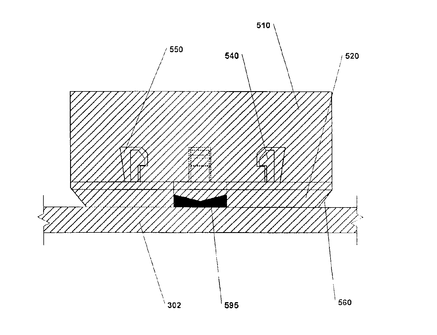
[0044]According to the present invention, the process for installing ceramic tiles on the surface of substrate is as follows. First, existing refractory and hexmetal mesh on the substrate 302, if any, should be removed. Following that, lower tile part 520 should be welded to the substrate 302 using plug weld 595 which is provided through the center plug welding orifice 530 to substrate 302. Welding can be limited to the plug area provided 530 or can extend along one or more chamfered edges 560 if desired.
[0045]Next, the upper tile part 510 is placed over lower tile part 520 with locking recesses 550 centered over the locking tabs 540 or the lower tile part 520. Next, a force is applied on the wear face (upper portion) of upper tile part 510 until it engages with lower tile part 520. In connection with the placement of tiles, male protrusions 565 should be aligned with and interlocked with female receptacles 570 to provide additional stability. The process is then repeated for each t...
PUM
 Abstract
Description
Claims
Application Information