Control system and method for starting a frozen fuel cell

a control system and fuel cell technology, applied in the field of fuel cells, can solve the problems of increased operating costs, reduced efficiency of fuel cell stack, increased production costs due to the larger components,

Inactive Publication Date: 2005-05-03
GM GLOBAL TECH OPERATIONS LLC
View PDF6 Cites 9 Cited by
  • Summary
  • Abstract
  • Description
  • Claims
  • Application Information

AI Technical Summary

Benefits of technology

[0009]A method and apparatus according to the present invention controls current that is supplied to a load by a fuel cell stack. A minimum voltage of a plurality of fuel cells in a fuel cell stack is monitored. The current load that is supplied by the fuel cell stack is increased if the minimum fuel cell voltage value exceeds a first voltage value.

Problems solved by technology

When fuel cell stacks are installed as powerplants in vehicles, the extra reactants that are supplied to the fuel cell stack require larger fuel cell stack components and decrease the efficiency of the fuel cell stack.
These factors lead to greater production costs due to the larger components.
Operating costs are also increased due to the additional reactant gas.
During testing to determine the precise amount of reactants that are required, the fuel cell stack is often operated in a low or relatively weak performance mode.
Sometimes the fuel cell voltage output drops to zero or reverses potential, both of which can cause damage the MEA of the fuel cell stack.
When the current load increases before thawing, individual fuel cells within the fuel cell stack may fail.
The failure of the individual fuel cells prevents the fuel cell stack from supplying the full rated current load.
The residual frozen water slows reaction rates because fewer active sites are available for reaction.
Rapid increases in the current load cannot be handled by the frozen fuel cell stack.

Method used


Image

  • Control system and method for starting a frozen fuel cell
  • Control system and method for starting a frozen fuel cell
  • Control system and method for starting a frozen fuel cell

Examples


Embodiment Construction

[0018]The following description of the preferred embodiment(s) is merely exemplary in nature and is in no way intended to limit the invention, its application, or uses.

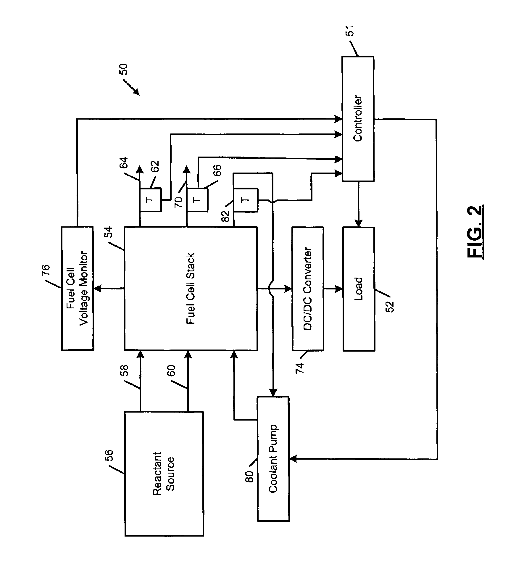
[0019]The fuel cell control system according to the present invention controls a current load that is supplied by the fuel cell by monitoring a minimum fuel cell voltage of fuel cells in the fuel cell stack. The minimum fuel cell voltage is compared to first and second voltage values. Based on a difference between the minimum fuel cell voltage and the first and second voltage values, the fuel cell control system increases, decreases or maintains the current load that is supplied by the fuel cell stack.

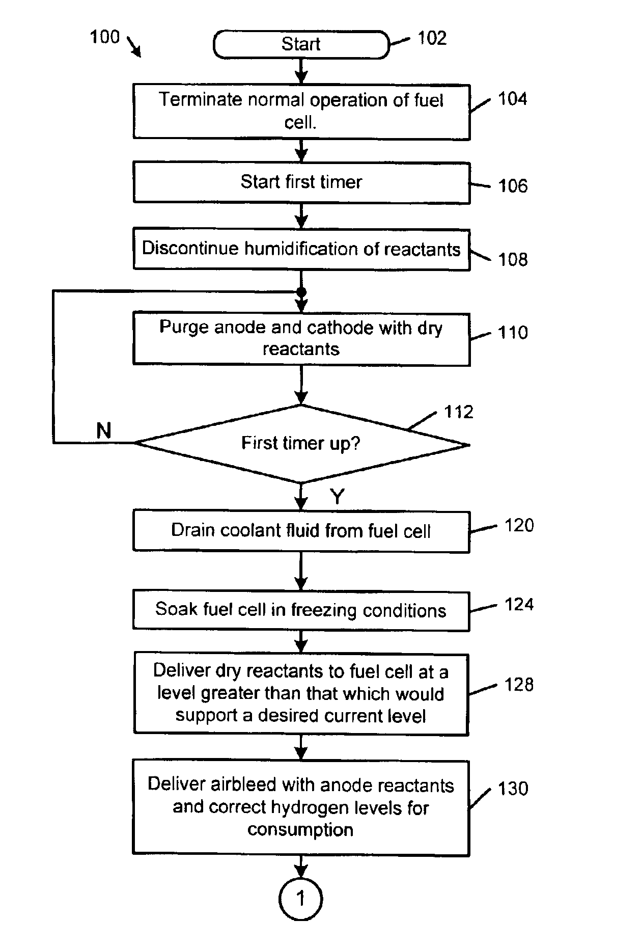
[0020]The fuel cell control system according to the present invention will be described in conjunction with a procedure for starting a frozen fuel cell. The control system, however, may also be used for other purposes. For example, the fuel cell control system can be used to monitor fuel cell stacks during developmental ...


PUM

PropertyMeasurementUnit
temperaturesaaaaaaaaaa
current densityaaaaaaaaaa

Abstract

A method for starting a frozen fuel cell stack includes discontinuing reactant humidification before shutting down the fuel cell stack. The anode and cathode are purged with the dry reactants. The fuel cell stack is soaked at freezing temperatures. During subsequent startup, dry reactants are initially delivered. An outlet temperature of the anode and a current load of the fuel cell stack are measured. The dry reactants are shut off when the temperature of the anode outlet or the current load reach predetermined values. The open circuit voltage potential of the fuel cells is monitored and compared to a first voltage value. When the open circuit voltage exceeds the first value, the fuel cell stack begins supplying current load. The current load of the fuel cell stack is increased or decreased based on a difference between the minimum voltage and a second voltage value.

Description

FIELD OF THE INVENTION[0001]The present invention relates to fuel cells, and more particularly to a control system and method for starting a frozen fuel cell.BACKGROUND OF THE INVENTION[0002]Fuel cells generate power that can potentially be used in a variety of different applications. Fuel cells may eventually replace internal combustion engines in automobiles and trucks. Fuel cells may also power homes and businesses. There are many different types of fuel cells. For example, a solid-polymer-electrolyte membrane (PEM) fuel cell includes a membrane that is sandwiched between an anode and a cathode. To produce electricity through an electrochemical reaction, hydrogen (H2) is supplied to the anode and air or oxygen (O2) is supplied to the cathode.[0003]In a first half-cell reaction, dissociation of the hydrogen (H2) at the anode generates hydrogen protons (H+) and electrons (e−). Because the membrane is proton conductive and dielectric, the protons are transported through the membrane...

Claims


Application Information

Patent Timeline
Patent Type & Authority Patents(United States)
IPC IPC(8): H01M8/04
CPCH01M8/04231Y02E60/50
Inventor THOMPSON, ERIC L.FUSS, ROBERT L.
Owner GM GLOBAL TECH OPERATIONS LLC
Why Eureka
Try Eureka