
Cables including fillers

a technology of fillers and cables, applied in the direction of insulated cables, capacitors, electrical equipment, etc., can solve the problems of difficult to achieve satisfactory and/or safe tasks, difficult to remove fillers, and normally redundant or superfluous fillers

Inactive Publication Date: 2005-05-03
RAYDEX INT LTD
View PDF15 Cites 57 Cited by
  • Summary
  • Abstract
  • Description
  • Claims
  • Application Information

AI Technical Summary

Benefits of technology

[0010]It is an object of the present invention to reduce the problems associated with conventional cables incorporating fillers, especially cables used for high speed data transmission.
[0012]The provision of points of weakness or discontinuities enables a portion of filler to be removed from the cable without the need for cutting. To remove a portion the filler is placed under tension, for example by pulling with finger and thumb or pliers. The filler can then be withdrawn from the cable up to the nearest discontinuity or point of weakness at which the filler will preferentially break. Since sharp tools are not required there is a reduced risk of accidental cable damage and personal injury.
[0019]Separating the pairs of wires helps to reduce the amount of crosstalk between them. To further reduce crosstalk an electromagnetic screen may be provided around one or more of the pairs for example by wrapping the pair with a conductive tape, for example, a metal tape or tape laminate. An aluminium / polyester laminate would be suitable.
[0023]The invention provides for the production of cables for high speed data transmission which may be more quickly, easily, safely and reliably installed than conventional cables.

Problems solved by technology

Where a cable is terminated, for example in a connecting device, the filler is normally redundant or superfluous.
In some cable and connector designs where space limitation, connection procedures, or specific performance requirements dictate, the task can be difficult to achieve satisfactory and / or safely.
The problem of filler removal is particularly acute with the type of cables used for high speed data transmission.
Disturbing the integrity of the twisted pair by displacement, bending, untwisting or other mechanical disturbance, may reduce cable performance significantly and irreparably.
Secondly, installation engineers wish to minimize the number of steps and the time involved in each termination, and removal of such components can be awkward, time consuming and therefore costly.

Method used


Image

  • Cables including fillers
  • Cables including fillers
  • Cables including fillers

Examples


Embodiment Construction

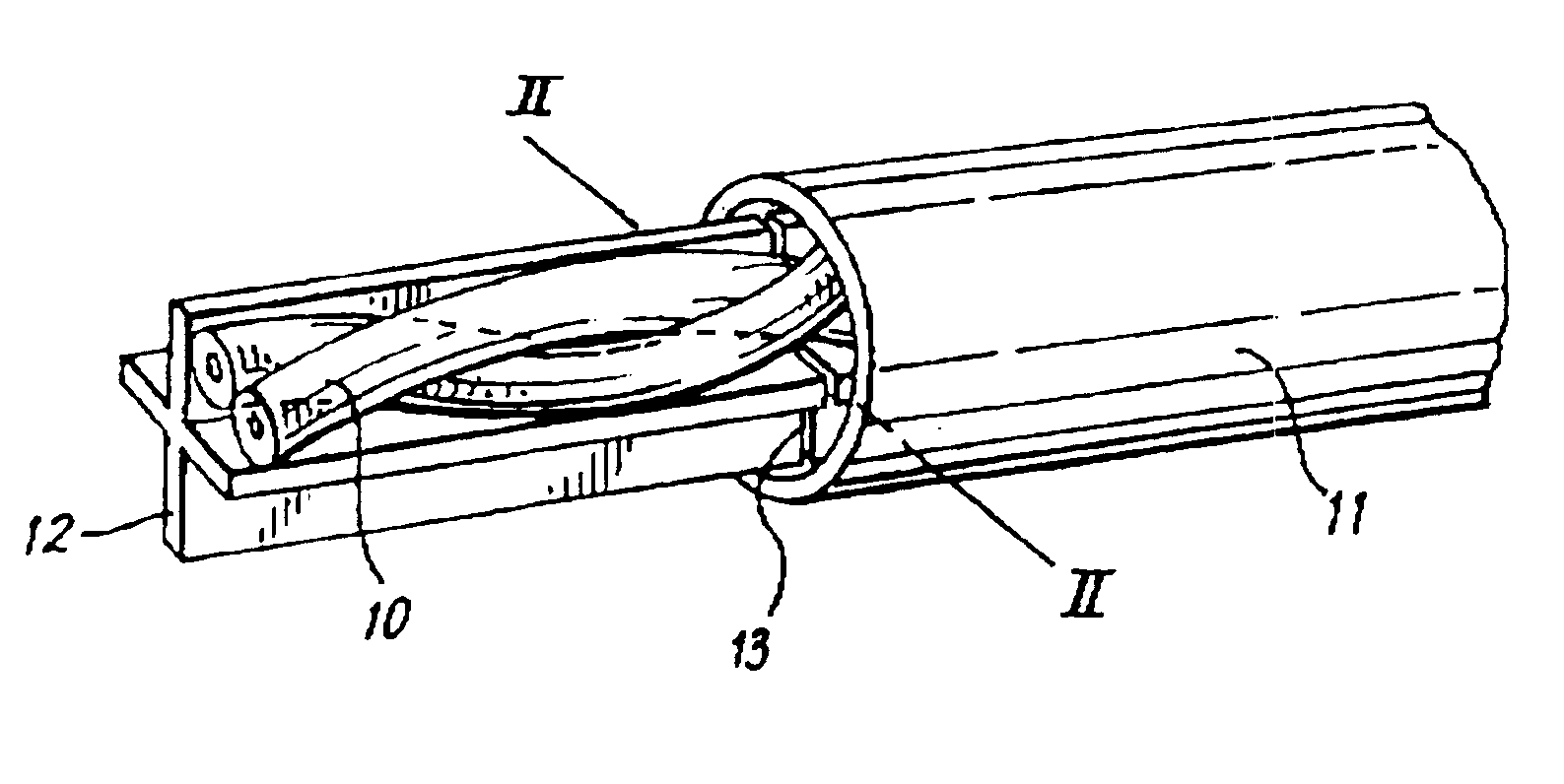
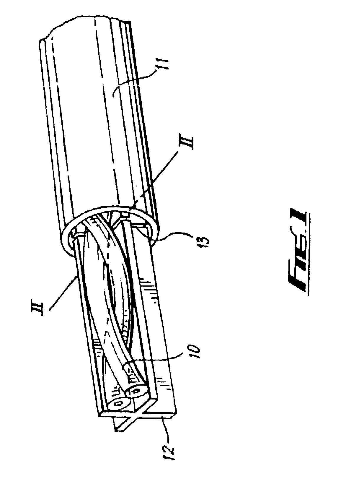
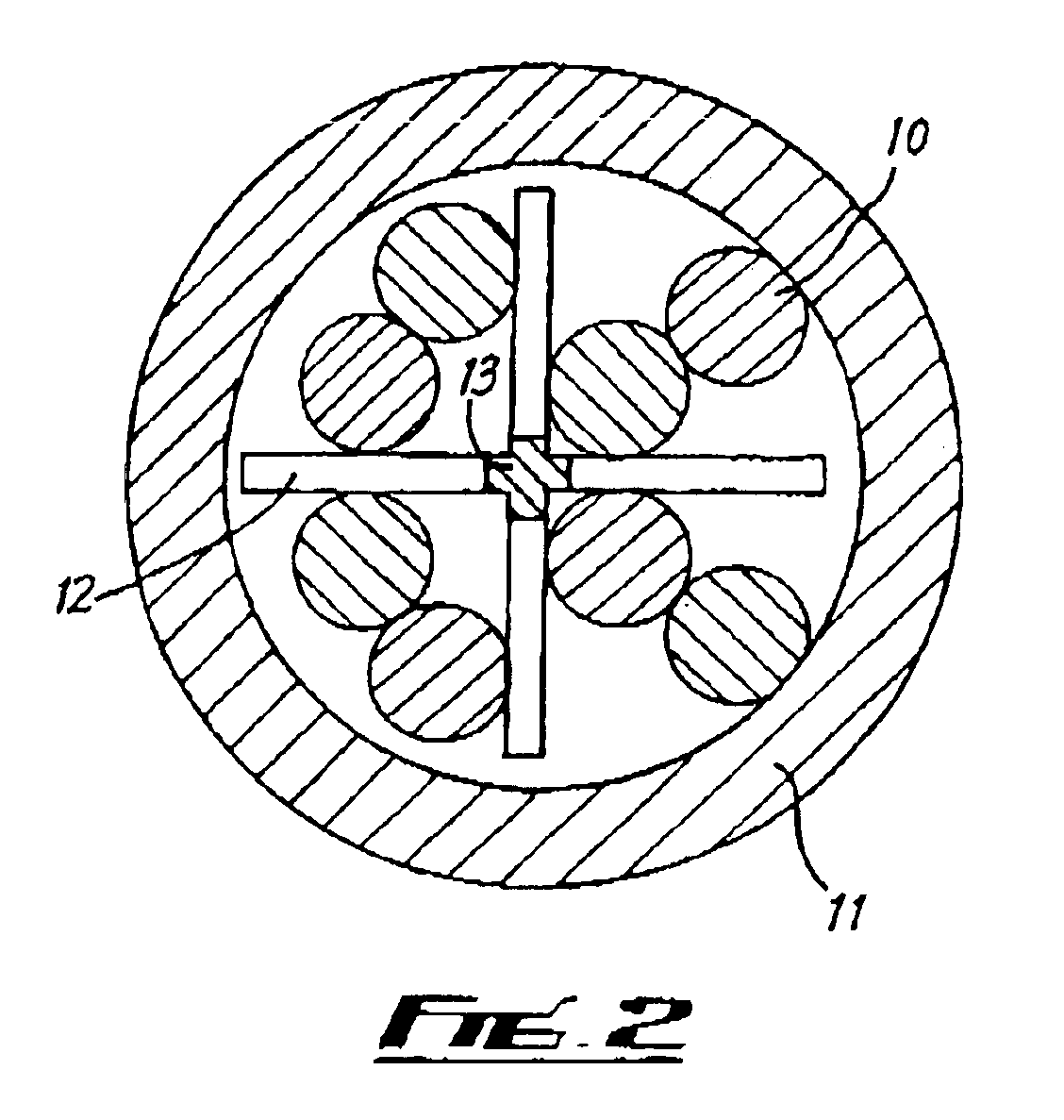
[0035]Referring to FIGS. 1 and 2, a cable comprises four pairs of twisted insulated electrical wires 10 (only one of which is shown in FIG. 1, for clarity) disposed in a plastic outer sheath 11. Also disposed in the outer sheath 11 is a cable filler 12 comprising an electrical grade polyethylene extrusion the cross section of which is cross-shaped with four substantially perpendicular arms which divide the space within the outer sheath 11 into four regions. The four pairs of wires 10 are respectively disposed in these regions. The filler 12 gives the cable structure as well as separating the four pairs of twisted wires 10 to reduce crosstalk between them.

[0036]In an alternative embodiment the filler 12 is formed from an electrically conductive material and therefore provides an electromagnetic screen between each twisted pair. This embodiment is capable of producing extremely low values for crosstalk over a wide frequency bandwidth.

[0037]At regular intervals along its length each ar...


PUM

PropertyMeasurementUnit
longitudinal tensionaaaaaaaaaa
plasticaaaaaaaaaa
electrically conductiveaaaaaaaaaa

Abstract

A cable includes a filler (12) including a plurality of points of weakness (13) or discontinuities spaced along its length. The points of weakness or discontinuities may be evenly spaced along the length of the cable and may be formed by partially or fully cutting through the filler. The filler may be formed from a plastics material and may be shaped, in cross section, to have a number of arms to enable it to separate other components of the cable. The filler may be electrically conducive or semi-conductive to enable it to act as screen between other components of the cable.

Description

RELATED APPLICATIONS[0001]Foreign priority benefits are claimed under 35 U.S.C. §119(a)-(d) or 35 U.S.C. §365(b) of United Kingdom application number 9924411.3, filed Oct. 16, 1999.BACKGROUND OF INVENTION[0002]1. Field of Invention[0003]The present invention relates to cables including fillers.[0004]2. Discussion of Related Art[0005]It is common for electrical and optical cables to include a filler or multiple fillers. Fillers typically comprise string or extruded plastic components which occupy space within the cable. They may be provided to enhance the overall shape of and / or positioning of other components, for example conductors or optical fibers, relative to each other within the cable, or to provide mechanical protection. For example, a central filler may be surrounded by cable components, or interstitial fillers may be provided between cable components to give a cable a substantially circular cross section.[0006]Where a cable is terminated, for example in a connecting device,...

Claims


Application Information

Patent Timeline
Patent Type & Authority Patents(United States)
IPC IPC(8): H01B11/06H01B11/08H01B11/02H01B7/18
CPCH01B11/08H01B11/06
Inventor PRESCOTT, STEPHEN JOHN
Owner RAYDEX INT LTD
Features
  • Generate Ideas
  • Intellectual Property
  • Life Sciences
  • Materials
  • Tech Scout
  • Unparalleled Data Quality
  • Higher Quality Content
  • 60% Fewer Hallucinations
Learn More