Resonator, filter, composite filter, transmitting and receiving apparatus, and communication apparatus

a technology of composite filter and resonator, which is applied in the direction of resonators, superconductors/hyperconductors, waveguides, etc., can solve the problems of increasing the conductor loss of the resonator, the temperature of the resonator electrode to exceed the critical temperature, and the conventional low-loss dielectric resonator to achieve the effect of stable communication characteristics

Inactive Publication Date: 2005-05-03
MURATA MFG CO LTD
View PDF5 Cites 10 Cited by
  • Summary
  • Abstract
  • Description
  • Claims
  • Application Information

AI Technical Summary

Benefits of technology

[0026]A communication apparatus according to the present invention includes the filter, the duplexer, the composite filter a...

Problems solved by technology

For example, a failure to cool the resonators due to a malfunction of the refrigerator, however, causes the temperature of the resonator electrodes to exceed the critical temperature.
Therefore, the conductor loss of the resonators is increased.
Such conventional low-...

Method used


Image

  • Resonator, filter, composite filter, transmitting and receiving apparatus, and communication apparatus
  • Resonator, filter, composite filter, transmitting and receiving apparatus, and communication apparatus
  • Resonator, filter, composite filter, transmitting and receiving apparatus, and communication apparatus

Examples


first embodiment

[0045]The configuration of a microstrip resonator according to the present invention will be described with reference to FIGS. 1A, 1B, 1C and 2.

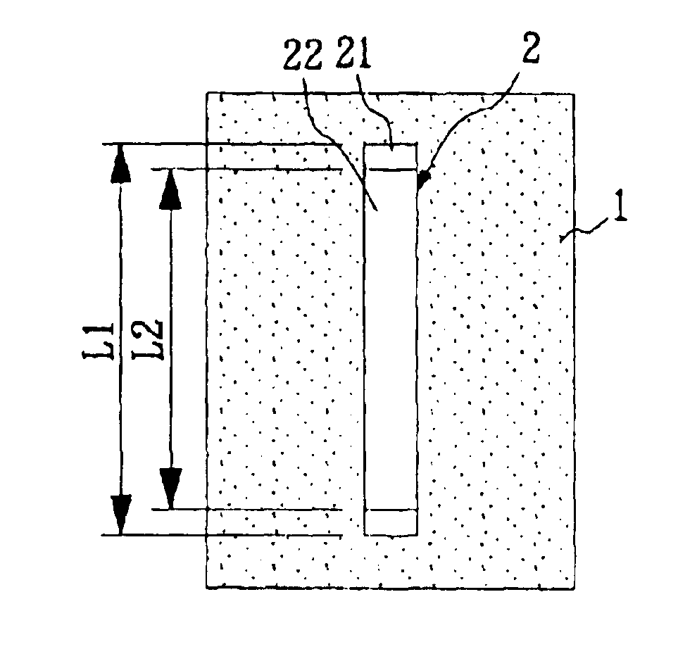
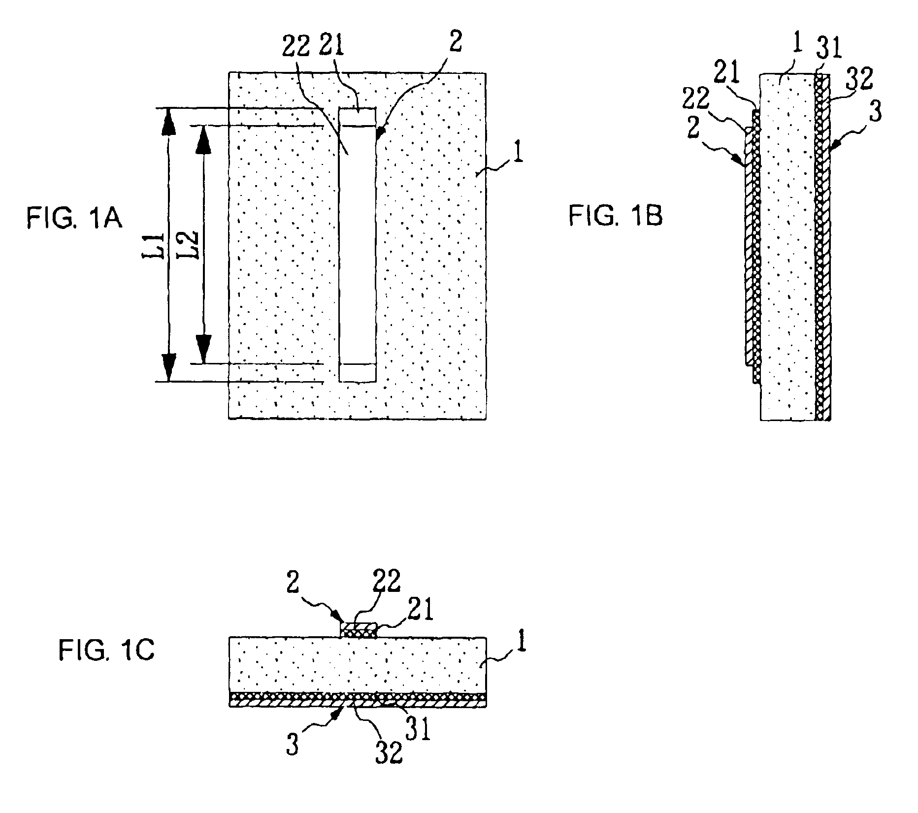
[0046]FIG. 1A is a top view of the microstrip resonator. FIG. 1B is a sectional view of the microstrip resonator taken along the longitudinal direction. FIG. 1C is a sectional view of the microstrip resonator taken along the lateral direction.

[0047]Referring to FIGS. 1A to 1C, a resonance electrode 2 is formed on a first main surface of a dielectric substrate 1. The resonance electrode 2 comprises an electrode film 21 made of a superconductor (hereinafter, referred to as a superconducting film 21) having a longitudinal length L1 and an electrode film 22 made of a metal (hereinafter, referred to as a metal film 22) having a longitudinal length L2 deposited in that order from the first main surface of the dielectric substrate 1. The length L1 of the superconducting film 21 is greater than the length L2 of the metal film 22. Thus, the supercond...

second embodiment

[0058]The configuration of a microstrip resonator according to the present invention will now be described with reference to FIGS. 3 and 4.

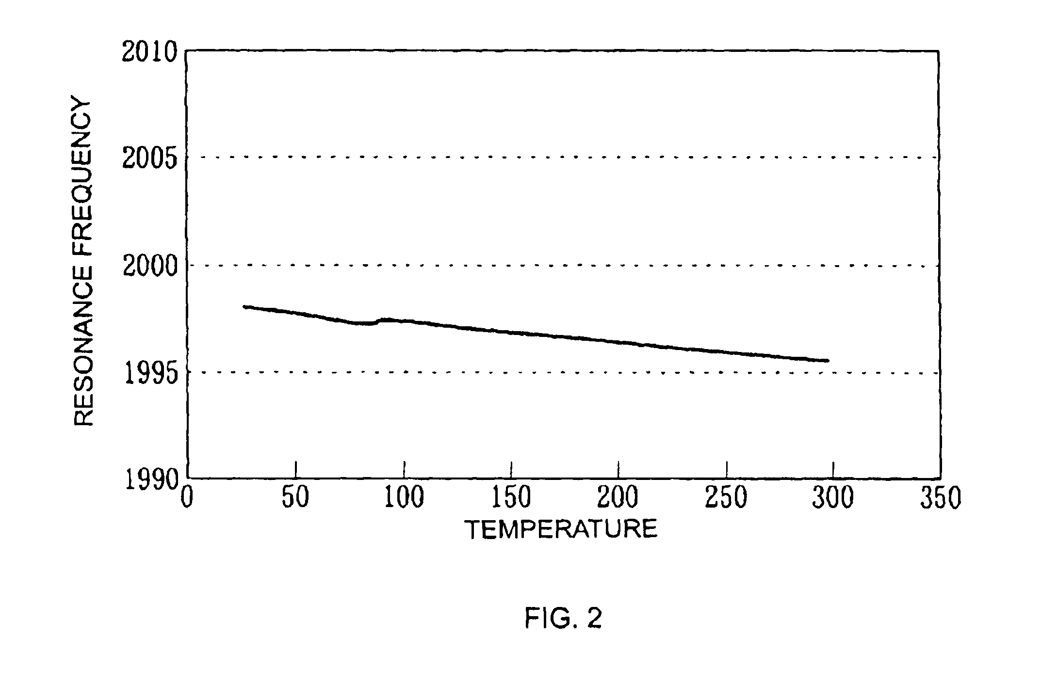
[0059]FIG. 3 shows the temperature characteristics of the dielectric constant of a dielectric used in the second embodiment. FIG. 4 shows the temperature characteristics of the resonance frequency of the resonator.

[0060]The configuration of the microstrip resonator according to the second embodiment is the same as in the first embodiment with the exception of the materials of the dielectric substrate 1. More specifically, only the temperature characteristics of the dielectric constant of the dielectric constituting the dielectric substrate 1 are different from those of the first embodiment.

[0061]The temperature coefficient of the dielectric constant of the dielectric used in the second embodiment is negative. For example, the temperature coefficient is −8 ppm / K, as shown in FIG. 3.

[0062]For a dielectric having such a negative temperature coeffici...

third embodiment

[0065]The configuration of a microstrip resonator according to the present invention will now be described with reference to FIGS. 5A, 5B, and 5C.

[0066]FIG. 5A is a top view of the microstrip resonator. FIG. 5B is a sectional view of the microstrip resonator taken along the longitudinal direction. FIG. 5C is a sectional view of the microstrip resonator taken along the lateral direction.

[0067]The dielectric, superconductor, and metal used in the third embodiment are the same as in the first embodiment.

[0068]The resonance electrode 2 is formed on a first main surface of the dielectric substrate 1. The resonance electrode 2 comprises a composite electrode film 23 having a predetermined longitudinal length and the superconducting films 21 having a predetermined length and connected to ends of the composite electrode film 23. The composite electrode film 23 is composed of a superconductor and a metal. The ground electrode 3 is formed over an entire second main surface of the dielectric s...


PUM


Abstract

A microstrip resonator including a dielectric substrate, a resonance electrode on a first main surface of the dielectric substrate, and a ground electrode over an entire second main surface of the dielectric substrate. The resonance electrode includes a superconducting film and a metal film deposited in that order. The ground electrode includes a superconducting film and a metal film deposited in that order. The superconducting film functions as an electrode in low-temperature operation below a critical temperature, and the metal film functions as an electrode in high-temperature operation at or above the critical temperature. The length of the superconducting film of the resonance electrode is set to be longer than that of the metal film of the resonance electrode, so that the resonance frequency in low-temperature operation is substantially equal to the resonance frequency in high-temperature operation.

Description

BACKGROUND OF THE INVENTION[0001]1. Field of the Invention[0002]The present invention relates to resonators, filters, duplexers, composite filter apparatuses, and transmitting and receiving apparatuses that are used in RF circuits of communication equipment, and to communication apparatuses that use the resonators, the filters, the duplexers, the composite filter apparatuses, and the transmitting and receiving apparatuses.[0003]2. Description of the Related Art[0004]Generally, resonators such as dielectric resonators provided with electrodes on dielectrics are used for microwave communication. The dielectric resonators are, for example, microstrip resonators and dielectric coaxial resonators.[0005]Along with the improved performance of communication apparatuses, low-loss characteristics of resonators are becoming more important. Dielectric resonators in which superconductors are used as electrodes have low conductor loss. For such resonators, however, in order to maintain low-loss c...

Claims


Application Information

Patent Timeline
IPC IPC(8): H01P1/213H01P1/203H01P7/08H01P7/04H01P1/20H01P1/205
CPCH01P1/20327H01P1/2056H01P7/082H01P7/04H01P3/081
Inventor MATSUI, NORIFUMIKINTAKA, YUJI
Owner MURATA MFG CO LTD
Why Eureka
Try Eureka