
Antenna unit stable in antenna characteristics and achievable in lengthening of life

a technology of antenna characteristics and stability, applied in the structure of radiating elements, substantially flat resonant elements, resonant antennas, etc., can solve the problems of difficult to achieve the effect of lengthening life, increasing the probability of failure of conduction, unstable antenna characteristics, etc., to achieve stability in antenna characteristics, reduce stress, and prolong li

Inactive Publication Date: 2005-05-03
ALPS ALPINE CO LTD
View PDF10 Cites 24 Cited by
  • Summary
  • Abstract
  • Description
  • Claims
  • Application Information

AI Technical Summary

Benefits of technology

[0008]The invention has been though of in view of such situation in the prior art, and has its object to provide an antenna unit, which is stable in antenna characteristics and can achieve lengthening of life.
[0010]When the projecting pieces of the shield casing are thus made adjacent to the sides of the dielectric board to positionally restrain the antenna element, even application of vibrations or the like causes no fear that the antenna element on the circuit board fluctuates in a direction of rotation, thus achieving stability in antenna characteristics and greatly reducing stress such as torsion or the like acting on the feeding pin and its soldered portions, so that lengthening of life is expectable. Also, since the number of parts is not increased, it is easy to avoid an increase in cost.
[0011]With such constitution, when a plurality of mount pieces are provided on the shield casing to be mounted on the circuit board and at least a part of the mount pieces serves as the projecting pieces, the mount work of the shield casing and the work of positioning the projecting pieces in a predetermined position can be done at the same time, which is preferable since the assembling quality can be prevented from being deteriorated by the projecting pieces.
[0012]Also, in the case where solder lands are provided on the sides of the dielectric board on the antenna element, and the solder lands are soldered to the projecting pieces, the antenna element is strongly fixed to the circuit board, whereby stability in antenna characteristics and lengthening of life can be further promoted.

Problems solved by technology

With the antenna unit of the prior art shown in FIG. 5, while the antenna element 3 is fixed to the circuit board 1 by soldering both ends of the feeding pin 8 to the patch electrode 7 and the amplifier 2, torque with the feeding pin 8 as an axis of rotation acts on the antenna element 3, which is fixed only at the feeding point, so that vibrations during traveling make the antenna element 3 liable to fluctuate on the circuit board 1 in a direction of rotation, such fluctuation giving rise to a cause for making antenna characteristics unstable.
Also, when the antenna element 3 fluctuates in the direction of rotation, stress such as torsion or the like acts on the feeding pin 8 and its soldered portions to cause a problem that a danger of failure in conduction is increased in likelihood and lengthening of life is hard to achieve.

Method used


Image

  • Antenna unit stable in antenna characteristics and achievable in lengthening of life
  • Antenna unit stable in antenna characteristics and achievable in lengthening of life
  • Antenna unit stable in antenna characteristics and achievable in lengthening of life

Examples


Embodiment Construction

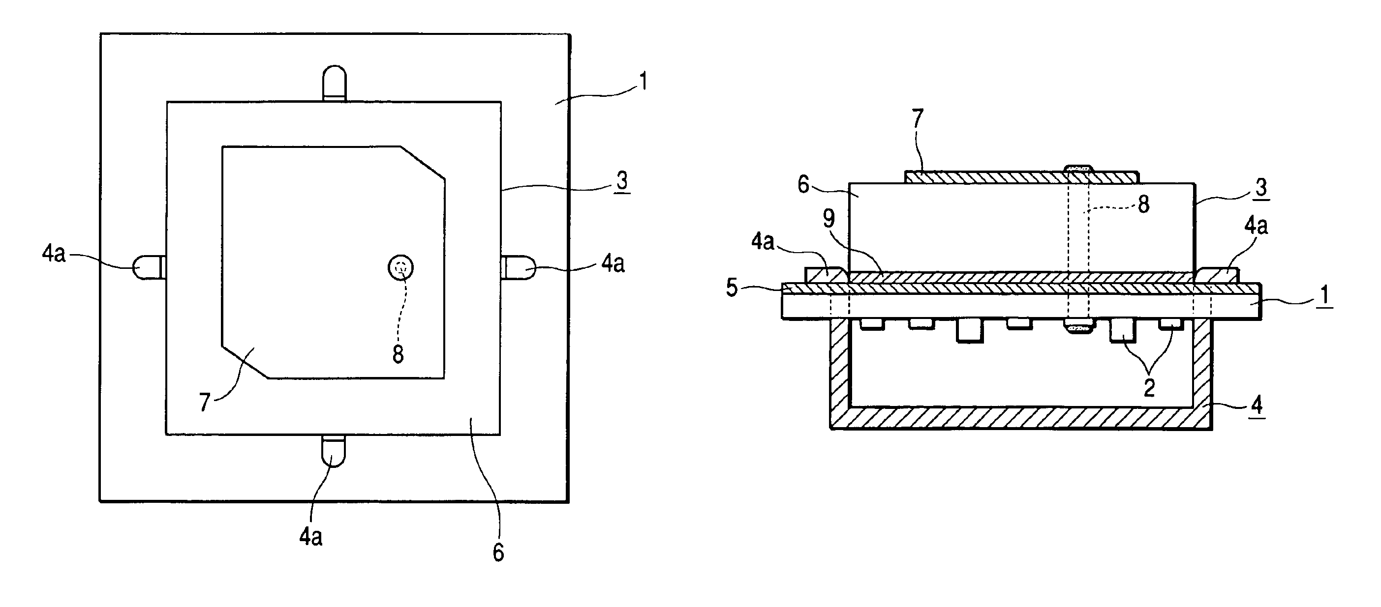
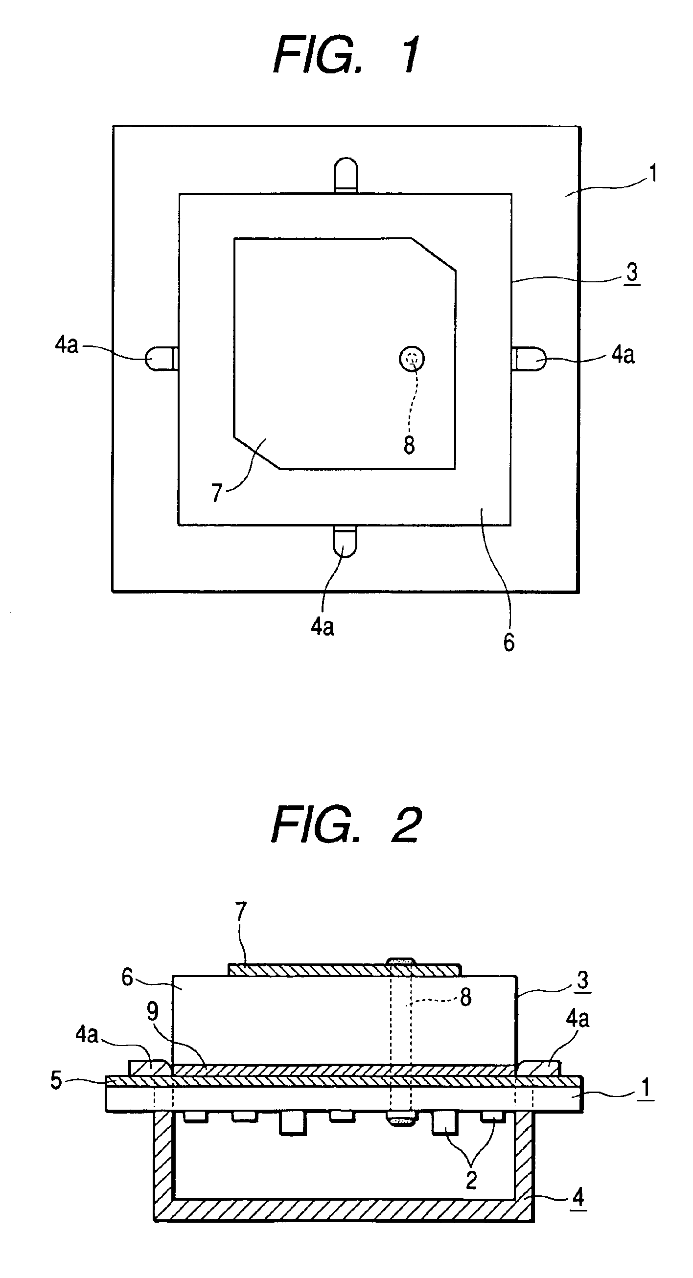
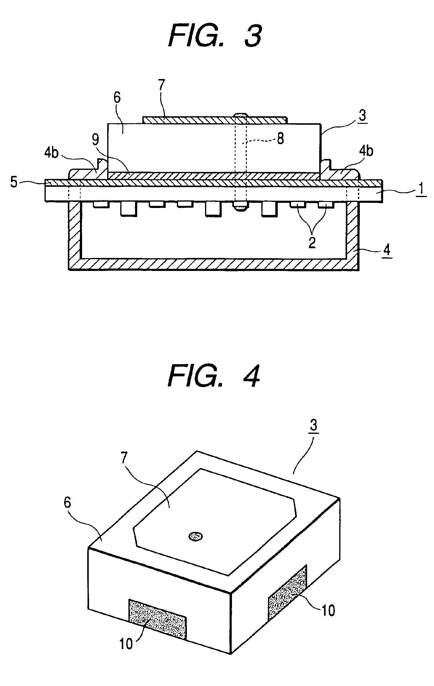
[0018]An explanation will be given to embodiments of the invention with reference to the drawings. FIG. 1 is a plan view showing an antenna unit according to an embodiment of the invention, FIG. 2 is a cross sectional view showing the antenna unit, FIG. 3 is a cross sectional view showing an antenna unit according to a further embodiment of the invention, and FIG. 4 is a perspective view showing an antenna unit according to a still further embodiment of the invention. In addition, those parts in these drawings, which correspond to those in FIG. 5, are denoted by the same reference numerals as those in FIG. 5, and duplication of an explanation is suitably omitted.

[0019]An antenna unit shown in FIGS. 1 and 2 is greatly different from the prior art (see FIG. 5) in that an antenna element (patch antenna) 3 is positionally restrained by mount pieces 4a of a shield casing 4. That is, like the prior art, the antenna unit is mainly composed of a circuit board 1 provided at a bottom surface ...


PUM


Abstract

At least a part of mount pieces of a shield casing is arranged in locations adjacent to sides of a dielectric board to positionally restrain an antenna element. Even when torque with a feeding pin as an axis of rotation acts on the antenna element, the antenna element does not move in a direction of rotation.

Description

BACKGROUND OF THE INVENTION[0001]1. Field of the Invention[0002]The present invention relates to a small-sized antenna unit mounted on a moving body, for example, vehicles or the like and suitable as antenna units for ITS (Intelligent Transport System) such as ETC (Estimated Time of Completion), VICS (Vehicle Information Communications System), or the like, or antenna units for GPS (Global Positioning System).[0003]2. Description of the Related Art[0004]The prior art of such kind of antenna unit is described in Japanese Unexamined Published Patent Application No. H9-223912 and so on. Such prior art will be described with reference to a cross sectional view of FIG. 5. An antenna unit shown in the figure is mainly composed of a circuit board 1 provided on a bottom surface thereof with an amplifier 2, an antenna element 3 mounted on the circuit board 1, and a shield casing 4 of metallic sheet mounted on the circuit board 1 to shield the amplifier 2.[0005]A ground conductor 5 is provide...

Claims


Application Information

Patent Timeline
Patent Type & Authority Patents(United States)
IPC IPC(8): H01Q1/00H01Q1/27H01Q1/52H01Q23/00H01Q9/04H01Q1/12H01Q1/32H01Q13/08
CPCH01Q1/27H01Q23/00H01Q9/0407H01Q1/526
Inventor SHIKATA, MASARU
Owner ALPS ALPINE CO LTD
Features
  • Generate Ideas
  • Intellectual Property
  • Life Sciences
  • Materials
  • Tech Scout
  • Unparalleled Data Quality
  • Higher Quality Content
  • 60% Fewer Hallucinations
Learn More