
Control and drive circuit arrangement for illumination performance enhancement with LED light sources

Inactive Publication Date: 2005-05-03
SAMSUNG DISPLAY CO LTD
View PDF13 Cites 192 Cited by
  • Summary
  • Abstract
  • Description
  • Claims
  • Application Information

AI Technical Summary

Benefits of technology

[0009]The invention comprises an LED backlight for an LCD display. The backlight may comprise, for example, an array or bank of red, green and blue (“RGB”) LEDs positioned adjacent to the rear substrate of the LCD, along with associated drive circuitry (including drive electronics). It may alternatively comprise an array or bank of RGB LEDs positioned adjacent to one or more sides or edges of the LCD, along with associated drive circuitry. As known in the art, waveguides or other optical elements direct the red, green and blue light generated to each pixel of the LCD. The LED backlight provides a simpler design that facilitates thin panel manufacture. It may also reduce or eliminate the need for certain optical elements required in side or edge backlighting, also facilitating manufacture.
[0013]The LED backlight also overcomes the disadvantages of the prior art CCFL backlights with respect to display of video data by an LCD display panel. As noted, the light output of the LED backlight has a response time on the order of microseconds using appropriate drive circuitry. Thus, the LED backlight may be readily switched on and off over a fraction of a video frame period, which is on the order of 8.3 ms (120 Hz frame rate), thus reducing or eliminating the artifacts created by the relatively slow response time of current LCD displays. In addition, because of the fast response time of the LED backlight, the color point and / or color content of the LED backlight may be adjusted to reflect the color point and / or color content of the video, something the CCFL backlight is incapable of. As noted, current LCDs have a response time on the order of 50 ms and thus cannot display every video frame, since a frame period is on the order of 8.3 ms. However, since the response time of the LED backlight may be on the order of microseconds, the output of the LED backlight may readily be adjusted for each video frame received. Thus, the color point and / or color content of the LED backlight may be adjusted to reflect the background color or color content of the image for each video frame received, even though the LCD cannot display all frames received. Thus, the LED backlight captures and uses some of the video data that is otherwise lost using current LCD displays.
[0014]In addition, an LED backlight may be used to provide the color required by each pixel of the LCD array, thus the color filters and sub-pixels of the LCD may be eliminated. For example, where the RGB LED backlight is located to the side or edge of the LCD panel, red, green and blue light may be generated in a rapid and repeating sequence and supplied (via associated waveguides and other optical components) to the pixels of the LCD. Each LCD pixel of the display may each be addressed for each successive color in the sequence to regulate the output of incident red, green and blue light in appropriate amounts to create the color in the image at the pixel location. The viewer's eye integrates the sequence of red, green and blue light metered by each LCD pixel to perceive the image on the screen.

Problems solved by technology

Thus, the response time of the light output by an LED is practically limited by the response time of the drive power supplied to the LED.

Method used


Image

  • Control and drive circuit arrangement for illumination performance enhancement with LED light sources
  • Control and drive circuit arrangement for illumination performance enhancement with LED light sources
  • Control and drive circuit arrangement for illumination performance enhancement with LED light sources

Examples


Embodiment Construction

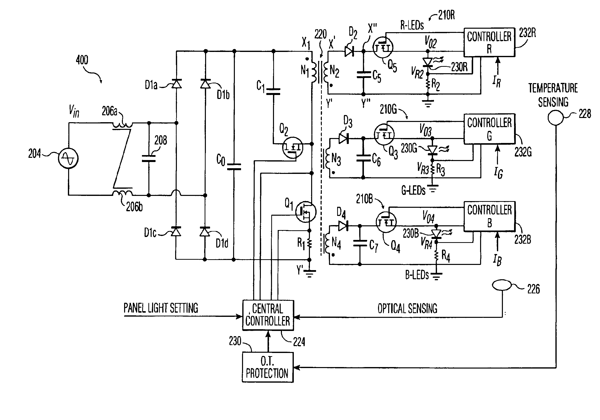
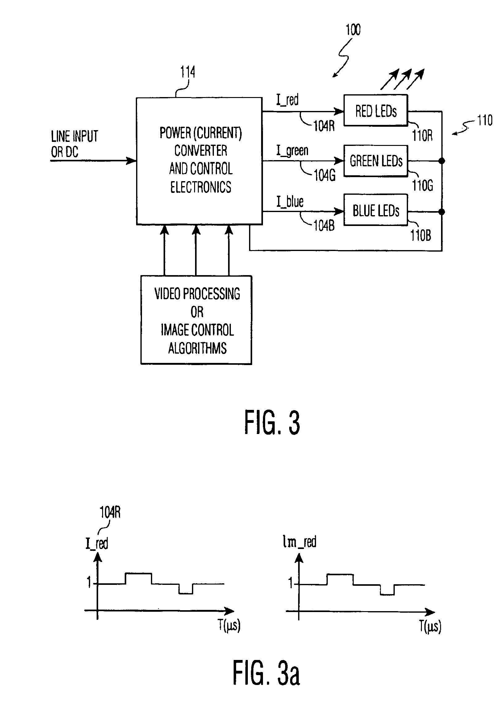
[0024]FIG. 3 is an embodiment of an LED backlight 100, including a circuit diagram of related driving circuitry, in accordance with the present invention. An array of RGB LEDs 110 are comprised of a sub-array of Red LEDs 110R, a sub-array of Green LEDs 100G and a sub-array of Blue LEDs 110B. The LEDs of sub-arrays 110R, 110G, 110B may be interleaved in a two-dimensional plane when, for example, the LED backlight is positioned adjacent the rear of the LCD panel. The LEDs of sub-arrays 110R, 110G, 110B may have other suitable spatial relationship. For example, the sub-arrays 110R, 110G, 110B may be comprised of one or more series of adjacent banks or strips of red, green and blue LEDs when, for example, the LED backlight is a side or edge backlight, where waveguides and / or other optical elements are used to guide the light generated to the back of the LCD pixels. Driving currents I_red 104R, I_green 104G and I_blue 104B are supplied to the red, green and blue sub-arrays of LEDs 110R, ...


PUM


Abstract

A backlight for an LCD display comprised of an array of LEDs. The backlight may be driven and controlled by a fast pulse power converter, thus providing a response time for the backlight on the order of microseconds. The backlight may thus be used for image display, for example, in the depiction of images in a video input to the LCD and removal of image artifacts.

Description

FIELD OF THE INVENTION[0001]The invention relates to backlighting of display panels, including the backlighting in LCD panels.BACKGROUND OF THE INVENTION[0002]A backlight is typically used to illuminate an LCD panel for information display. A typical LCD, such as an active matrix LCD, is comprised of liquid crystal disposed between two substrates. Adjacent to one substrate is a thin film common electrode and adjacent to the other is an array of thin film electrodes. Each electrode in the array is connected to one or more thin active elements and address lines, which serve to regulate the voltage applied to the electrode. The liquid crystal disposed between each pixel electrode and the common electrode comprises a pixel of the LCD. The electrode of the array for a given pixel is referred to below as a “pixel electrode”.[0003]In general, liquid crystal of a pixel of an LCD will pass incident light because of a helical alignment of the liquid crystal molecules working in conjunction wi...

Claims


Application Information

Patent Timeline
IPC IPC(8): G09G3/34H05B33/02H05B33/08G02F1/133G02F1/13357H05B44/00
CPCG09G3/3413H05B33/0818H05B33/0857H05B33/0869G09G2310/0235G09G2320/0261G09G2320/041G09G2320/062Y02B20/346G09G2320/0666G09G2320/064H05B45/22Y02B20/30H05B45/385H05B45/28G02F1/1335
Inventor BRUNING, GERTCHANG, CHIN
Owner SAMSUNG DISPLAY CO LTD
Learn More