Fixing unit

a fixing unit and heat sink technology, applied in the field of heat sinks, can solve the problems of uneven temperature at a part of the metallic roller or film, long heating up time, and frequency difference in the power flowing in the coil, so as to prevent flicker and suppress interference noise.

Inactive Publication Date: 2005-05-03
KK TOSHIBA +1
View PDF22 Cites 48 Cited by
  • Summary
  • Abstract
  • Description
  • Claims
  • Application Information

AI Technical Summary

Benefits of technology

[0019]It is an object of the present invention to provide a fixing unit of the induction heatin...

Problems solved by technology

Thus, it is known that the warming up takes a long time.
There is a problem peculiar to a fixing unit used in a copying machine, since the size of a fixing paper (the paper pass width) is not even, the temperature at a part of the metallic roller or film becomes uneven.
Thus, a frequency difference occurs in the power flowing in each coil, and an interference noise (whine) occurs.
In the driving method disclosed by the Jpn. Pat. Appln. KOKAI Publication No. 2001-312178, there is a problem that a device which detects the...

Method used


Image

  • Fixing unit
  • Fixing unit
  • Fixing unit

Examples


Embodiment Construction

[0053]Hereinafter, an example of the induction heating fixing unit according to the present invention will be explained with reference to the accompanying drawings.

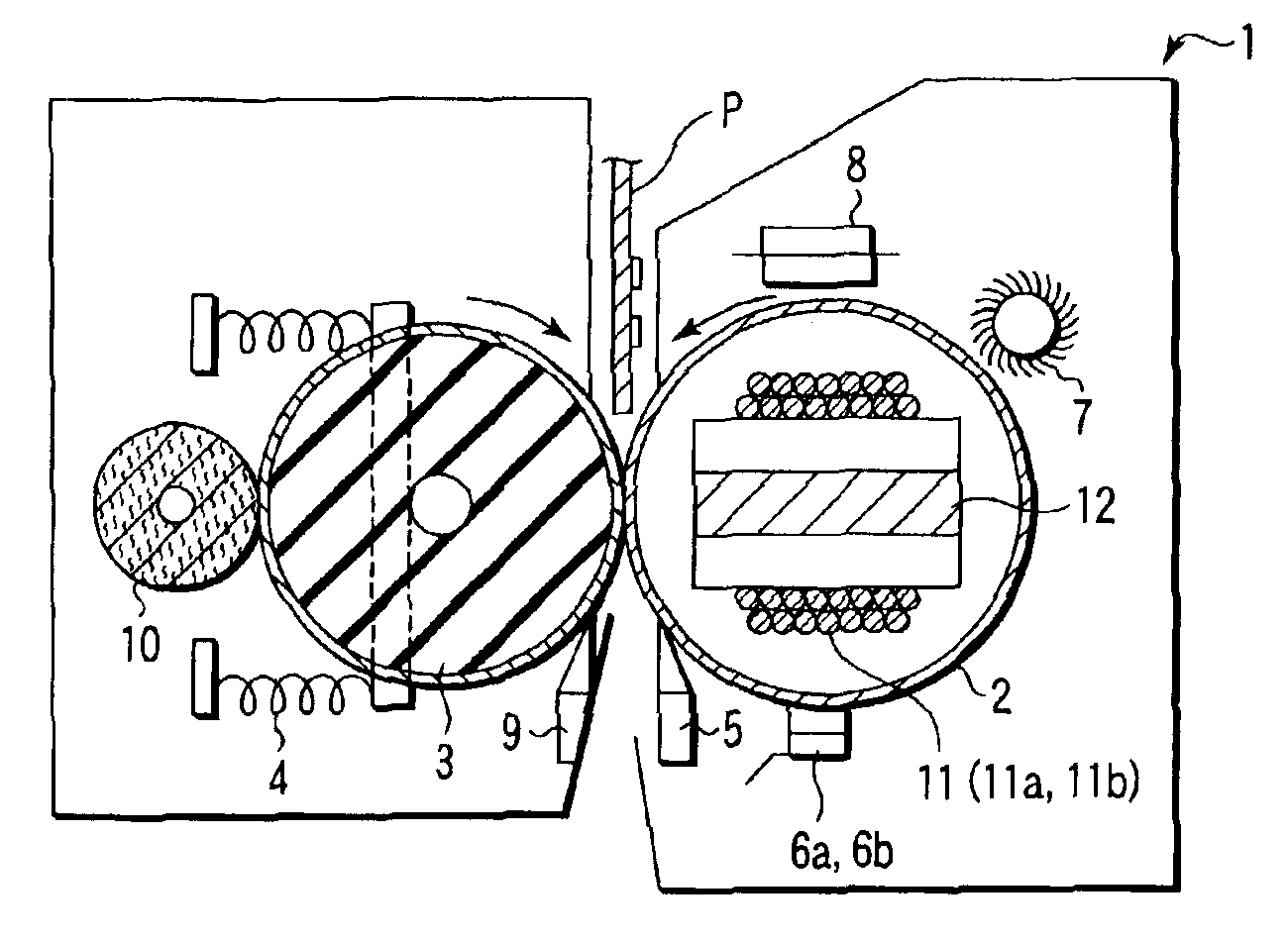
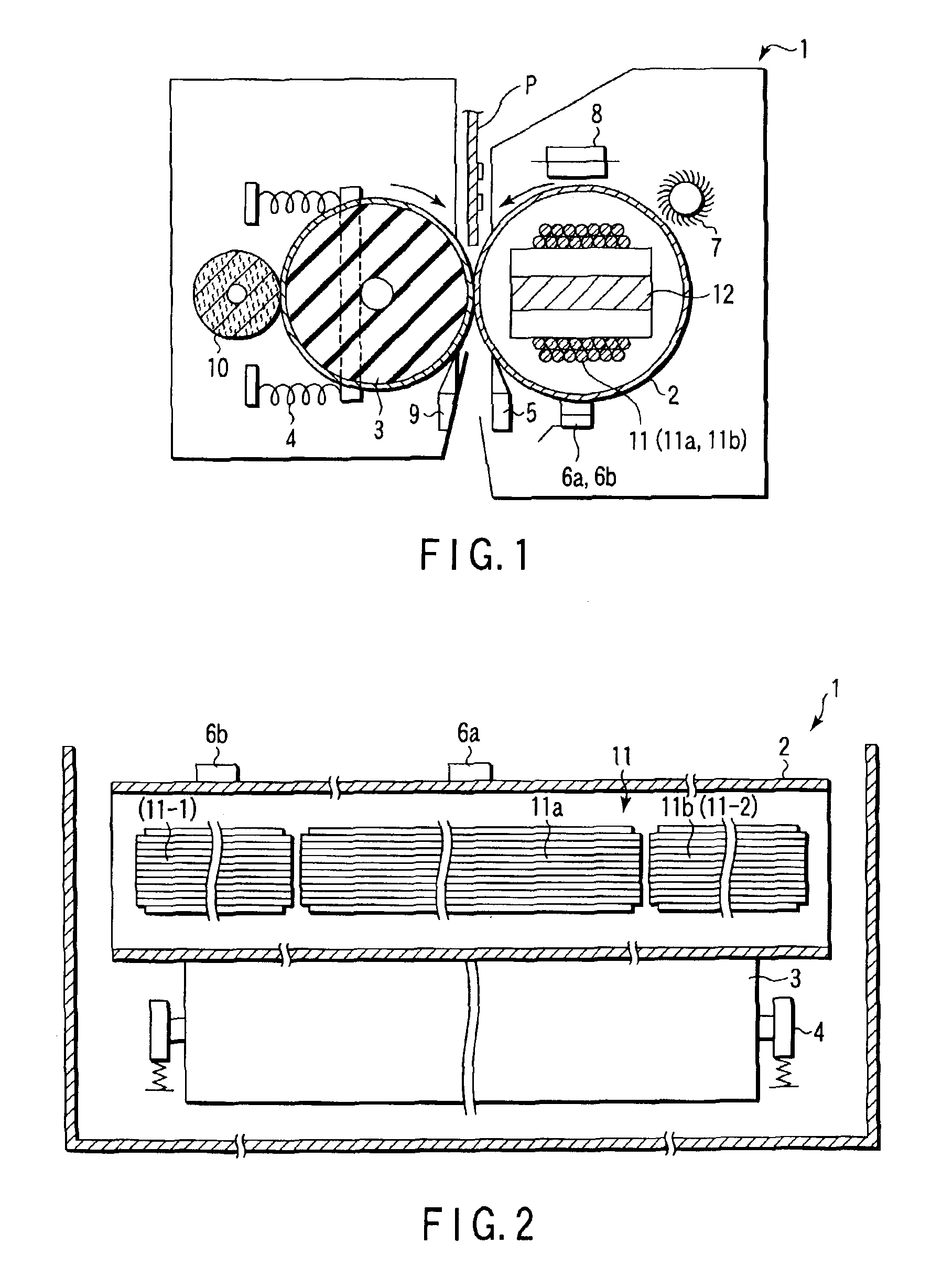
[0054]FIG. 1 is a schematic cross sectional view showing the fixing unit of the invention, cut almost the center in the longitudinally direction. FIG. 2 is a schematic plan view showing the fixing unit of FIG. 1, with the covers not explained in detail removed, and viewed from the plan direction.

[0055]A fixing unit 1 includes a heating (fixing) roller 2 with the diameter of about 50 mm, and a press roller 3 with the diameter of about 50 mm.

[0056]The fixing roller 2 is a metallic hollow cylinder with the thickness of 1.5 mm. Iron is used in this embodiment, but stainless steel, aluminum or stainless steel-aluminum alloy can be used. The fixing roller 2 is about 340 mm long in this example.

[0057]On the surface of the fixing roller 2, a not-shown releasing layer is formed fluoric resin such as ethylene tetrafluoride (Teflon ...


PUM


Abstract

A fixing device of the present invention has first and second thermistors which detect the temperatures at predetermined positions in the longitudinally direction of a heating roller, first and second coils which can increase independently the temperatures at the center and the end of the heating roller, a driving circuit which supply power alternately to the coils, first and second switching circuits which supply a predetermined power to each coil, a control unit, and a temperature detection circuit.

Description

CROSS-REFERENCE TO RELATED APPLICATIONS[0001]This application is based upon and claims the benefit of priority from the prior Japanese Patent Application No. 2002-152675, filed May 27, 2002, the entire contents of which are incorporated herein by reference.BACKGROUND OF THE INVENTION[0002]1. Field of the Invention[0003]The present invention relates to a heating unit using induction heating, and more particularly, to a fixing unit which fixes toner as a visualizing agent melt at predetermined temperature usable for an electrophotographic copying machine or printer.[0004]2. Description of the Related Art[0005]A fixing unit incorporated in a copying machine using an electrophotographic process fixes melted toner on a fixing material by heating and pressing. As a method of heating toner usable for the fixing unit, a method using the heat radiated from a filament lamp and a flash heating method using a flash lamp as a heat source are known well.[0006]However, the fixing unit using a fila...

Claims


Application Information

Patent Timeline
IPC IPC(8): G03G15/20H05B6/06H05B6/14H05B6/44
CPCG03G15/2042G03G2215/2016
Inventor KINOUCHI, SATOSHITAKAGI, OSAMU
Owner KK TOSHIBA
Why Eureka
Try Eureka