Wind tunnel test section model support structure with front edge bionic noise reduction structure

A technology of wind tunnel test and support structure, which is applied in aerodynamic test, machine/structural component test, instrument, etc. It can solve the problem that the background noise in the wind tunnel test section is not effectively suppressed, the noise control of the model support is difficult, and the turbulence Intensity and radiation noise problems, etc., to achieve the effect of improving the wind tunnel test environment, improving accuracy, and improving the test environment

Inactive Publication Date: 2021-04-09
NORTHWESTERN POLYTECHNICAL UNIV
View PDF9 Cites 2 Cited by
  • Summary
  • Abstract
  • Description
  • Claims
  • Application Information

AI Technical Summary

Problems solved by technology

[0005] (1) At the leading edge of the scimitar that is not connected to the 10° cone, the impedance suddenly changes from a fluid domain to a solid domain, which will generate a large leading edge noise
There is no effective noise reduction measure on the noise transmission path at the leading edge of the scimitar. The turbulence intensity and radiation noise at this position are very large, so that a large amount of noise generated by the scimitar is transmitted to the inside of the test section, thus making the background noise of the wind tunnel test section not effectively suppressed;
[0006] (2) The turbulent noise source mechanism of the model support in the wind tunnel test section is complex, and the noise radiation interweaves and interacts with complex fluid mechanics problems such as turbulence and unsteady flow, making it very difficult to control the noise of the model support

Method used


Image

  • Wind tunnel test section model support structure with front edge bionic noise reduction structure
  • Wind tunnel test section model support structure with front edge bionic noise reduction structure
  • Wind tunnel test section model support structure with front edge bionic noise reduction structure

Examples


Embodiment Construction

[0026] Describe below in conjunction with specific embodiment, embodiment does not constitute limitation of the present invention:

[0027] In this embodiment, a model support structure in the wind tunnel test section with a leading edge bionic noise reduction configuration proposed by the present invention is used to describe the working mode of the noise reduction process of the model support structure in the wind tunnel test section.

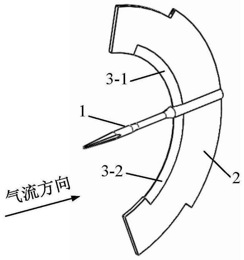
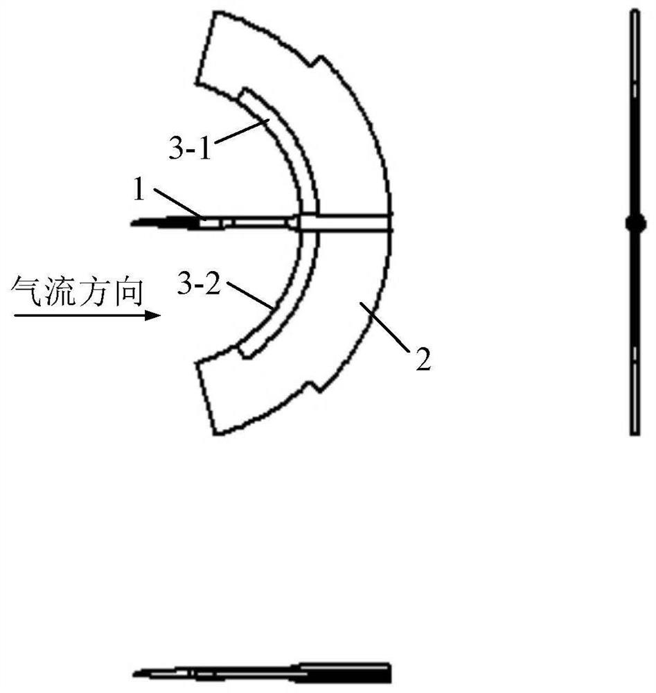
[0028] refer to figure 1 and figure 2 In this embodiment, a model support structure of a wind tunnel test section with a leading edge bionic noise reduction configuration includes a 10° cone 1 of the model support and a scimitar 2 connected to the 10° cone from upstream to downstream of the airflow.

[0029] The upper part 3-1 of the front edge of the scimitar and the lower part 3-2 of the front edge of the scimitar that are not connected with the 10° cone are both bionic configurations of the front edge, which can be designed as a zigzag ...


PUM


Abstract

The invention provides a wind tunnel test section model support structure with a front edge bionic noise reduction structure. The wind tunnel test section model support structure sequentially comprises a 10-degree cone of a model support and a bent knife tightly connected with the 10-degree cone from the upstream to the downstream of airflow. The front edge part of the bent knife structure has a certain wedge degree, and the remaining parts are equal in thickness. The bent knife is in a smooth streamline shape and is in mirror symmetry about the axis of the 10-degree cone. The bent knife structure is tightly connected with the 10-degree cone. When a wind tunnel works, airflow passes through a contraction section and enters a test section, and in the test section, the airflow firstly flows through the test model supported on the model support and then flows through the 10-degree cone and the bent knife; and then the airflow enters the wind tunnel diffusion section. The part, not connected with the 10-degree cone, of the bent blade front edge is designed to be of a sawtooth-shaped structure or a wavy structure, the two bent blade front edge structures reduce front edge interference noise by weakening the response of the bent blade to incoming flow turbulence, tail edge self-noise is restrained by influencing the stability of a boundary layer through a flow direction vortex at a wave trough, background noise of a wind tunnel test section is reduced, and the acoustic performance of the wind tunnel is improved.

Description

technical field [0001] The invention relates to the technical field of noise reduction in a wind tunnel test section, in particular to a model support structure in a wind tunnel test section with a leading edge bionic noise reduction configuration. Background technique [0002] Due to the need to support the model, a model support is installed in the wind tunnel test section. When the high-speed air flow in the tunnel passes through the surface of the model support, aerodynamic noise will be generated, and these aerodynamic noises are an important part of the background noise of the wind tunnel. Excessive background noise will seriously affect the accuracy of the collected data. At the same time, it will arouse the chattering response of the model and the support, cause structural fatigue damage, and cause damage to the operation control system of the wind tunnel and near-field operators. Therefore, it is particularly necessary to reduce the noise of the model support, but ...

Claims


Application Information

Patent Timeline
Patent Type & Authority Applications(China)
IPC IPC(8): G01M9/04G01M9/00
CPCG01M9/04G01M9/00
Inventor 盛美萍张瑞瑞王晨王震霄
Owner NORTHWESTERN POLYTECHNICAL UNIV
Why Eureka
Try Eureka