Method of manufacturing optical fiber preform

Inactive Publication Date: 2005-05-10
SUMITOMO ELECTRIC IND LTD
View PDF21 Cites 0 Cited by
  • Summary
  • Abstract
  • Description
  • Claims
  • Application Information

AI Technical Summary

Benefits of technology

[0014]In one aspect of the present invention, the turning position of the reciprocation movement may be shifted at constant intervals from the beginning position in a constant direction to a predetermined point, and then the turning position of the reciprocation may be shifted at constant intervals in the opposite direction to return to the beginning position. The recoprocating movement velocity may be constant from the beginning to the

Problems solved by technology

Japanese Patent Application Laid-Open No. 3-228845 does not disclose any method for determining such target weight.
The laid-open patent application does not disclose any method for determining a target weight in which glass particles accumulating at the ta

Method used


Image

  • Method of manufacturing optical fiber preform
  • Method of manufacturing optical fiber preform
  • Method of manufacturing optical fiber preform

Examples


Example

EXAMPLE 1

[0055]As shown in FIG. 6, four glass synthesis burners 71 arranged at intervals of 200 mm were traversed reciprocally over the length (600 mm) of the effective portion 63 of a starting rod 62 plus the width (1000 mm) of the burner array, and altering the outer diameter of a starting rod and the glass particles deposition time, an experiment was performed to measure the outer diameters of the resultant optical fiber preforms. While each burner is located opposite the effective portion of the starting rod, an equal quantity of SiCl4 74 was supplied to each burner. In this example, the traverse velocity of the starting rod was 740 mm / min. The results are as shown in Table I.

[0056]TABLE IOuter diameter ofGlass deposition timeOuter diameter of opticalstarting rod (mm)(minute)fiber preform (mm)40.04424129.5438.3424128.5139.5452131.7837.71452130.139.88482133.8638.05482132.7530.24482131.0230.08512136.2529.97560138.49

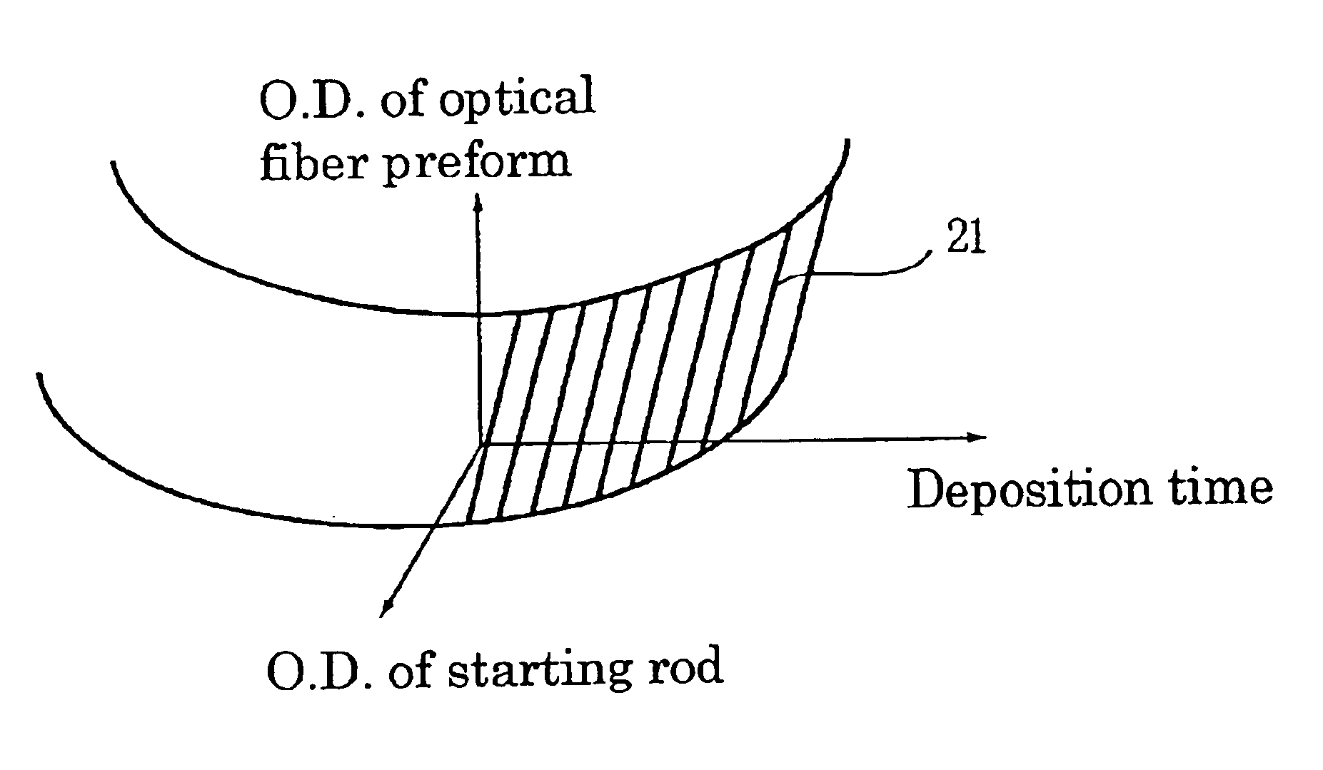
[0057]The relationship between the three variables was approximate...

Example

EXAMPLE 2

[0061]As shown in FIG. 6, four glass synthesis burners 71 arranged at intervals of 200 mm were traversed reciprocally over the length of the effective portion 63 of a starting rod 62 +1000 mm so as to deposit glass particles. The target jacketing ratio was 3.0 times, and the timing to end the deposition of glass particles was determined by four methods using: (1) a predetermined weight, (2) a predetermined number of turns, (3) a predetermined outer diameter of a soot glass deposit body, and (4) a method according to the present invention.

[0062]Here, (1) is a conventional method performed in the past: first the volume of a jacketing layer to be deposited is calculated beforehand from the outer diameter of a starting rod, and the jacketing ratio, and then the corresponding weight of glass particles to be deposited is calculated by multiplying the volume and the bulk density such that the deposition of glass particles is stopped when glass particles have been deposited to the ...

Example

EXAMPLE 3

[0066]As shown in FIG. 6, four glass synthesis burners 71 arranged at intervals of 200 mm were traversed reciprocally over the length of the effective portion 63 of a starting rod 62 +1000 mm such that glass particles were deposited by 1600 turns. The outer diameter of the starting rod and the traverse velocity were modified for the experiments, and the outer diameters of the optical fiber preforms were measured. The results are as shown in Table II.

[0067]TABLE IIOuter diameter of starting rod 20 20 20 30 30 30(mm)Traverse velocity (mm / min)703803903703803903Outer diameter of optical fiber142133120153147133preform (mm)

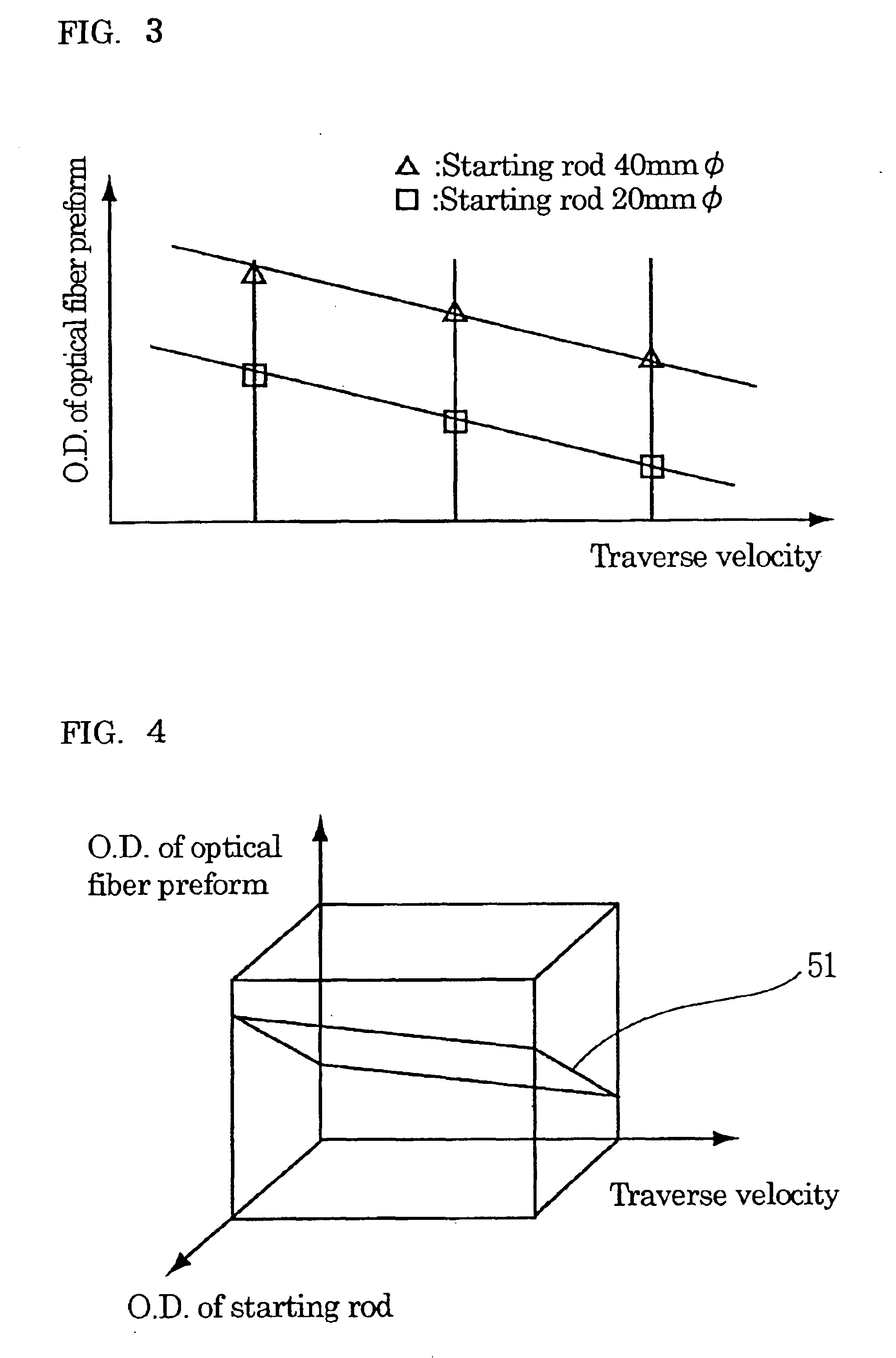
[0068]The results of these experiments were approximated with the plane, the coefficients were determined by the least squares method, and the following formula 3 was obtained:

T=11.68×R−9.22×S+1783.82  (Formula 3)

[0069]Next, the deposition of glass particles was performed on a starting rod having an outer diameter of 40 mm so that the outer diameter of an optic...


PUM

PropertyMeasurementUnit
Diameteraaaaaaaaaa
Diameteraaaaaaaaaa
Diameteraaaaaaaaaa

Abstract

A method for producing an optical fiber preform is provided in which the variation of the outer diameter in the longitudinal direction is minimized and a target quantity of glass is accumulated as a whole. Based on a predetermined relationship between three variables: the outer diameter of a starting rod being a first variable, the outer diameter of an optical fiber preform a second variable, and the timing for ending the glass particles depositing process a third variable, the starting rod and burners are subjected to relative reciprocating movement so as to deposit glass particles on the starting rod until the timing for ending the depositing process, and then the resulting deposit body is vitrified. The third variable may be the traverse velocity, the glass particles deposition time, or the weight of a soot glass deposit body.

Description

BACKGROUND OF THE INVENTION[0001]1. Field of the Invention[0002]The present invention relates to a method of manufacturing an optical fiber preform by an OVD method, and more particularly to a method for producing an optical fiber preform in which the variation of outer diameter in the longitudinal direction is minimized without decreasing the deposition speed and a target quantity of glass is achieved as a whole.[0003]2. Description of the Background Arts[0004]Japanese Patent Application Laid-Open No. 3-228845 discloses a method for manufacturing a large-sized optical fiber preform at high speed by an OVD method. In the disclosed method, a plurality of burners for synthesizing glass particles are arranged in a row at constant intervals, and the row of burners and a starting rod, which are opposed to each other, are reciprocated relatively so as to produce a soot glass deposit body by depositing glass particles around the starting rod which is rotating, and then the soot glass depos...

Claims


Application Information

Patent Timeline
IPC IPC(8): C03B37/014G02B6/00
CPCC03B37/0142C03B37/01493C03B2207/70C03B2207/52C03B2207/66C03B2207/36Y02P40/57G02B6/00
Inventor OOISHI, TOSHIHIROOHGA, YUICHIYOKOYAMA, YOSHIONAKAMURA, MOTONORI
Owner SUMITOMO ELECTRIC IND LTD
Why Eureka
Try Eureka