A cooling roller device for wire drawing tractor and its using method and application

A cooling roller and tractor technology, which is applied in the directions of stretch spinning, textile and paper making, rayon filament physical therapy, etc., can solve the problems affecting the quality of fiber filament/film products, etc., and achieves simple structure, convenient use, and increased cooling. effect of effect

Active Publication Date: 2022-07-26
TAIAN HAIDAI ROPE MACHINERY SCI TECH
View PDF11 Cites 0 Cited by
  • Summary
  • Abstract
  • Description
  • Claims
  • Application Information

AI Technical Summary

Problems solved by technology

[0005] Therefore, how to use cold water to cool down the surface of the traction roller in the rotating state, so as to avoid the high temperature of the traction roller surface from affecting the product quality of the fiber filament / film, has become a technical problem that needs to be solved urgently.

Method used


Image

  • A cooling roller device for wire drawing tractor and its using method and application
  • A cooling roller device for wire drawing tractor and its using method and application
  • A cooling roller device for wire drawing tractor and its using method and application

Examples


Embodiment 1

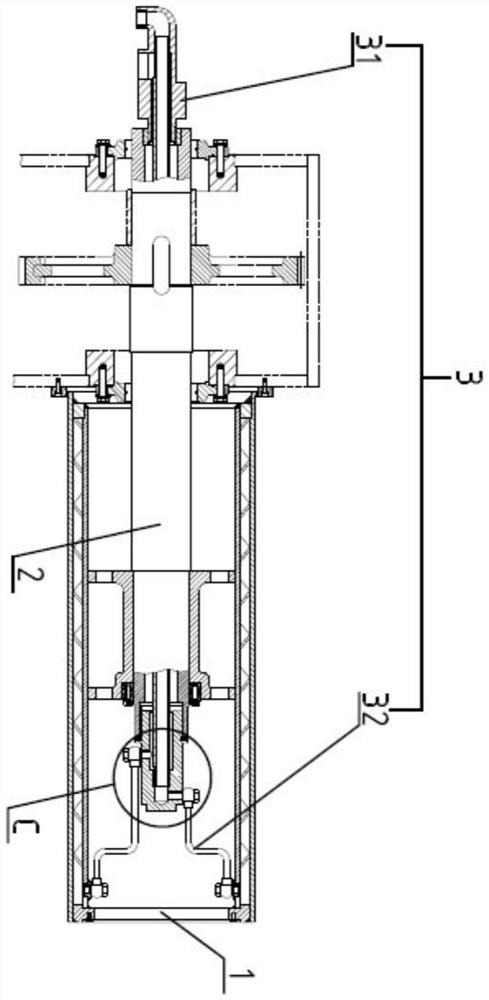
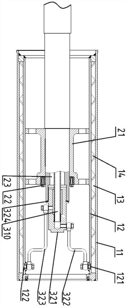
[0057] like Figure 1-6Shown a kind of cooling roller device for wire drawing tractor, comprises cooling roller 1, is connected with cooling roller 1 and is used for the cooling roller shaft 2 that transfers rotational torque to cooling roller 1, and described cooling roller 2 is sleeved on cooling roller 2. Inside the roller 1 , the cooling roller 1 includes an outer roller body 11 and an inner roller body 12 coaxially sleeved inside the outer roller body 11 , and a cooling roller fixedly connected to the inner roller body 12 is arranged inside the cooling roller 1 The shaft base 21, the cooling roller shaft base 21 and the cooling roller shaft 2 are fixedly connected by the expansion sleeve 22; it also includes a water circulation pipeline system 3 connected with the cooling roller 1 and the cooling roller 2;

[0058] An annular cooling water flow chamber 13 is formed between the outer roller body 11 and the inner roller body 12 , and the cooling water only flows inside the ...

Embodiment 2

[0074] The same parts of this embodiment and Embodiment 1 will not be repeated, and the differences are:

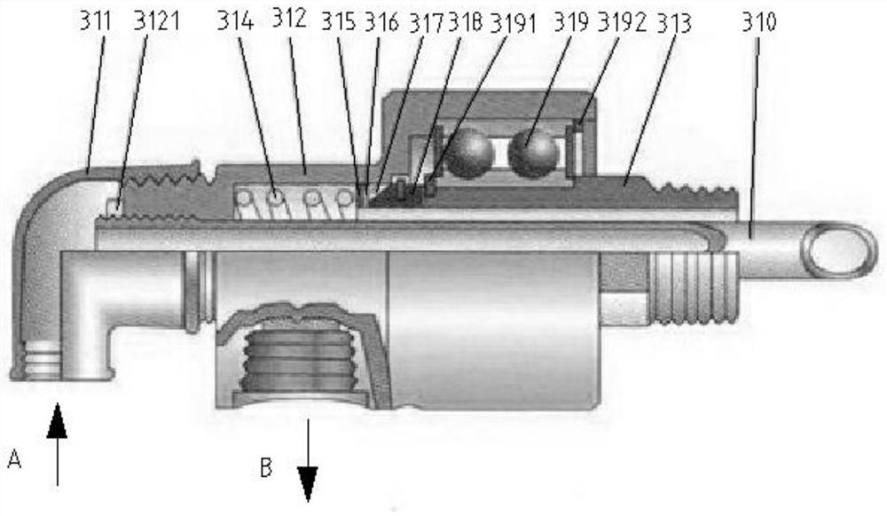
[0075] like Figure 7 As shown, through the elbow 311, the shell 312, the hollow shaft 313 and the inner tube 310 of the cooling roller 2 in sequence, it is divided into a first inner tube 3101 and a second inner tube 3102, the first inner tube 3101 and the elbow The water inlet A and the water inlet pipe assembly 322 communicate with each other, and the second inner pipe 3102 communicates with the elbow water outlet B and the water outlet pipe assembly 323 .

[0076] The cooling water flows into the first inner pipe 3101 through the elbow water inlet A, and flows into the cooling roller 1 through the water inlet pipe assembly 322. After heat exchange, it flows into the second inner pipe 3102 through the water outlet pipe assembly 323, and flows out through the elbow water outlet B .


PUM


Abstract

The invention relates to the technical field of cold water rolls, in particular to a cooling roll device used in a wire drawing tractor and a method of use and application thereof. It includes a cooling roller, a cooling roller shaft connected with the cooling roller and used to transmit rotational torque to the cooling roller, and a water circulation pipeline system connected with the cooling roller and the cooling roller; the cooling roller includes an outer roller body, a coaxial sleeve An annular cooling water flow cavity is formed between the outer roll body and the inner roll body, and the cooling water flow cavity is provided with a spiral groove; the inside of the cooling roll shaft is provided with A hollow cavity; the water circulation pipeline system communicates the cooling water flow cavity and the hollow cavity. The invention is simple in structure and convenient to use, keeps the surface temperature constant during the operation of the cooling roller, avoids the surface temperature of the roller from rising due to frictional heat generation, reduces the shrinkage and deformation of fiber / film, and improves product quality.

Description

technical field [0001] The invention relates to the technical field of cold water rolls, in particular to a cooling roll device used in a wire drawing tractor and a method of use and application thereof. Background technique [0002] Plastic wire drawing machine is a special equipment used in the plastic products industry to produce various hollow, solid round wires or flat wires with polyester, nylon, polyethylene, polypropylene, polyester chips, etc. as raw materials for deep processing. Among them, the traction roller is the most important. The drawing process of the drawing roller determines the thickness, smoothness and toughness of the drawn plastic wire. [0003] At present, the conventional drawing roller is connected by the drawing roller and the drawing roller shaft, and is rotated at the required speed under the driving of the motor to draw the fiber / film to the required diameter / thickness. The traction roller is simple in structure and widely used. However, dur...

Claims


Application Information

Patent Timeline
Patent Type & Authority Patents(China)
IPC IPC(8): D01D5/16D01D10/00
CPCD01D5/16D01D10/00
Inventor 徐建湘吕衍华孙昊
Owner TAIAN HAIDAI ROPE MACHINERY SCI TECH
Why Eureka
Try Eureka