A New Circulating Spherical Shell Device

A circulating spherical shell technology, which is applied in the field of new circulating spherical shell devices, can solve the problems of affecting the temperature field distribution of the heating plate and difficulty

Active Publication Date: 2021-04-23
广东立佳实业有限公司
View PDF5 Cites 0 Cited by
  • Summary
  • Abstract
  • Description
  • Claims
  • Application Information

AI Technical Summary

Problems solved by technology

However, due to the heat capacity and compaction effect of the heating film will affect the overall temperature field distribution of the heating plate
Therefore, the operation is difficult

Method used


Image

  • A New Circulating Spherical Shell Device
  • A New Circulating Spherical Shell Device
  • A New Circulating Spherical Shell Device

Examples


Embodiment Construction

[0043] The following will clearly and completely describe the technical solutions in the embodiments of the present invention with reference to the accompanying drawings in the embodiments of the present invention. Obviously, the described embodiments are only some, not all, embodiments of the present invention. Based on the embodiments of the present invention, all other embodiments obtained by persons of ordinary skill in the art without creative efforts fall within the protection scope of the present invention.

[0044] In describing the present invention, it is to be understood that the terms "opening", "upper", "lower", "thickness", "top", "middle", "length", "inner", "surrounding" etc. Indicating orientation or positional relationship is only for the convenience of describing the present invention and simplifying the description, and does not indicate or imply that the components or elements referred to must have a specific orientation, be constructed and operated in a sp...


PUM


Abstract

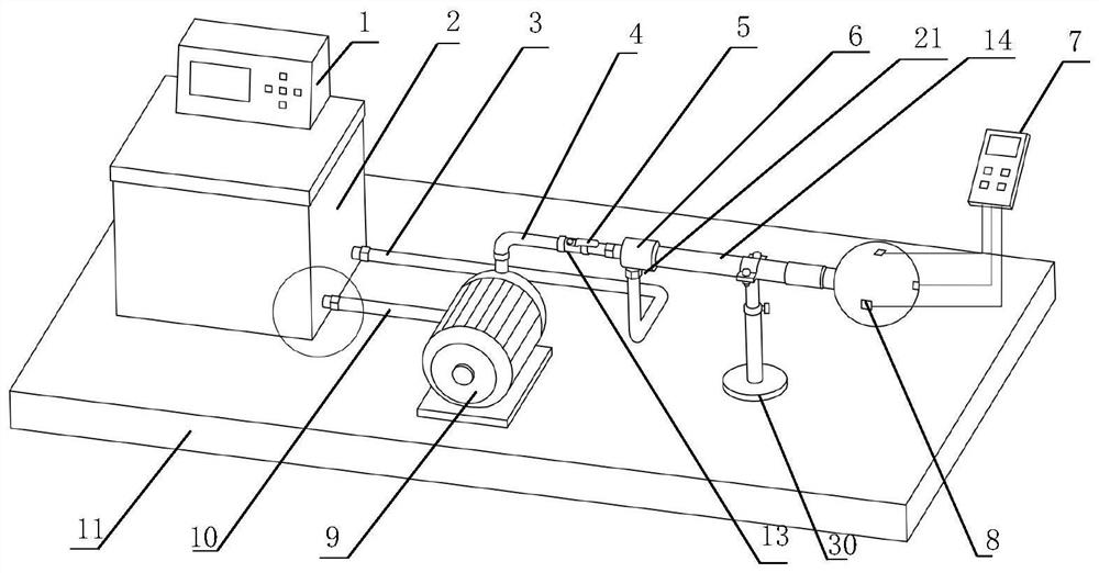
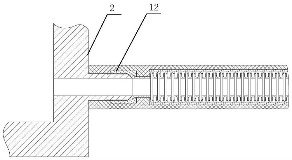
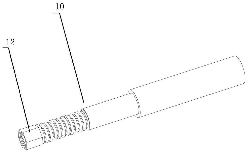
The invention discloses a new circulating spherical shell device, which includes a spherical shell filled with constant temperature oil, a sensor, a temperature acquisition and display instrument and a workbench. One side of the spherical shell is provided with a second inner tube leading to constant temperature oil, the second inner tube is placed horizontally, and the upper end of the inner wall of the spherical shell is provided with a rectangular oil return pipe for recovering constant temperature oil; through the spherical shell filled with constant temperature oil, the constant temperature The temperature conduction of the oil achieves a constant and uniform temperature on the surface of the spherical shell, forming a heat source with a constant and uniform surface temperature.

Description

technical field [0001] The invention relates to a heat source device, in particular to a novel circulating spherical shell device. Background technique [0002] The wire heat source usually uses a hot wire made of nickel-chromium alloy wire or iron-chromium-lead alloy wire to clamp the middle part of two identical workpieces for heating, and a temperature sensor is arranged at a certain distance from the hot wire and parallel to the hot wire. In some ideal cases, the diameter of the hot wire of the wire heat source can be infinitely small and the length is infinitely long. However, the smaller the diameter of the hot wire used in practical applications, the higher the processing technology requirements, and the strength of the hot wire is too thin. to guarantee. Therefore, the diameter of the heating wire used in the actual use of the centerline heat source has a certain size. In the initial stage of use, the heating wire itself will absorb a certain amount of heat to raise...

Claims


Application Information

Patent Timeline
Patent Type & Authority Patents(China)
IPC IPC(8): F24H7/00F24H9/00F24H9/20G01K13/00G01K13/02
Inventor 陈清华王建刚王皖楠
Owner 广东立佳实业有限公司
Why Eureka
Try Eureka