Solid melting furnace equipment and solid melting method

A kind of equipment and furnace technology, which is applied in the field of solid melting furnace equipment and solid melting treatment equipment, can solve the problems of short heating time, poor solid melting effect, high cost, etc., achieve the effect of ensuring uniformity and reliability, and reducing the time for entering the water from the furnace

Pending Publication Date: 2019-12-27
SHANGHAI ELECTRIC CABLE RES INST
View PDF0 Cites 2 Cited by
  • Summary
  • Abstract
  • Description
  • Claims
  • Application Information

AI Technical Summary

Problems solved by technology

[0003] Another solid melting process is that the wire and rod materials are continuously solid melted online, and the material will not be oxidized. However, this process is rapid heating at high temperature online, and the heating time is short, which leads to poor solid melting effect of some materials and cannot be applied. This process uses air cooling to quickly cool down and solidify, which consumes a lot of gas and costs high

Method used


Image

  • Solid melting furnace equipment and solid melting method
  • Solid melting furnace equipment and solid melting method
  • Solid melting furnace equipment and solid melting method

Examples


Embodiment Construction

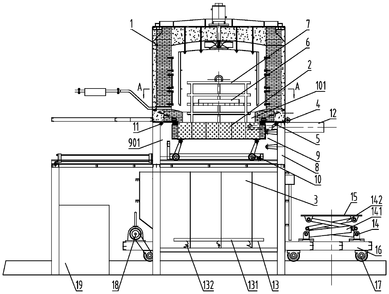
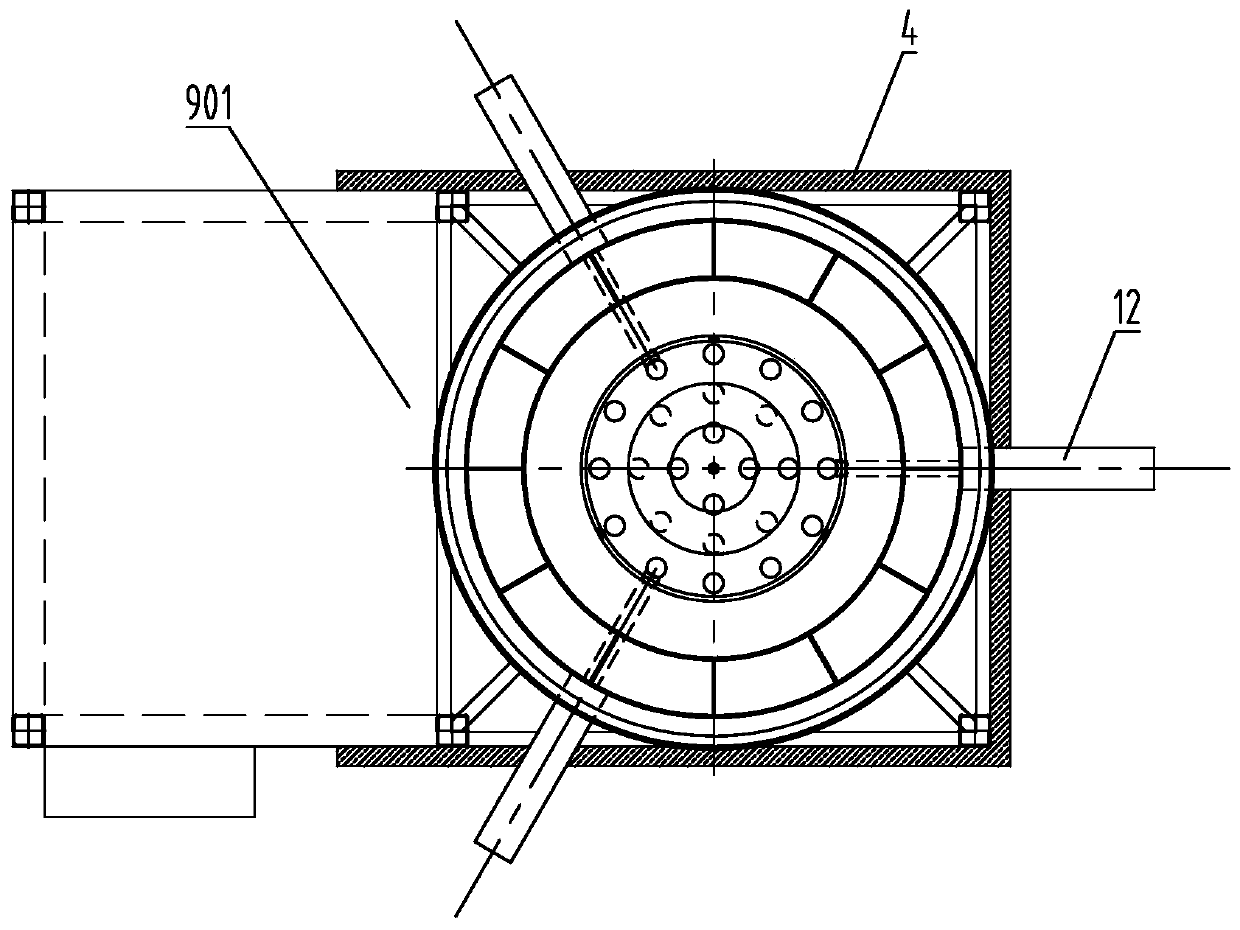
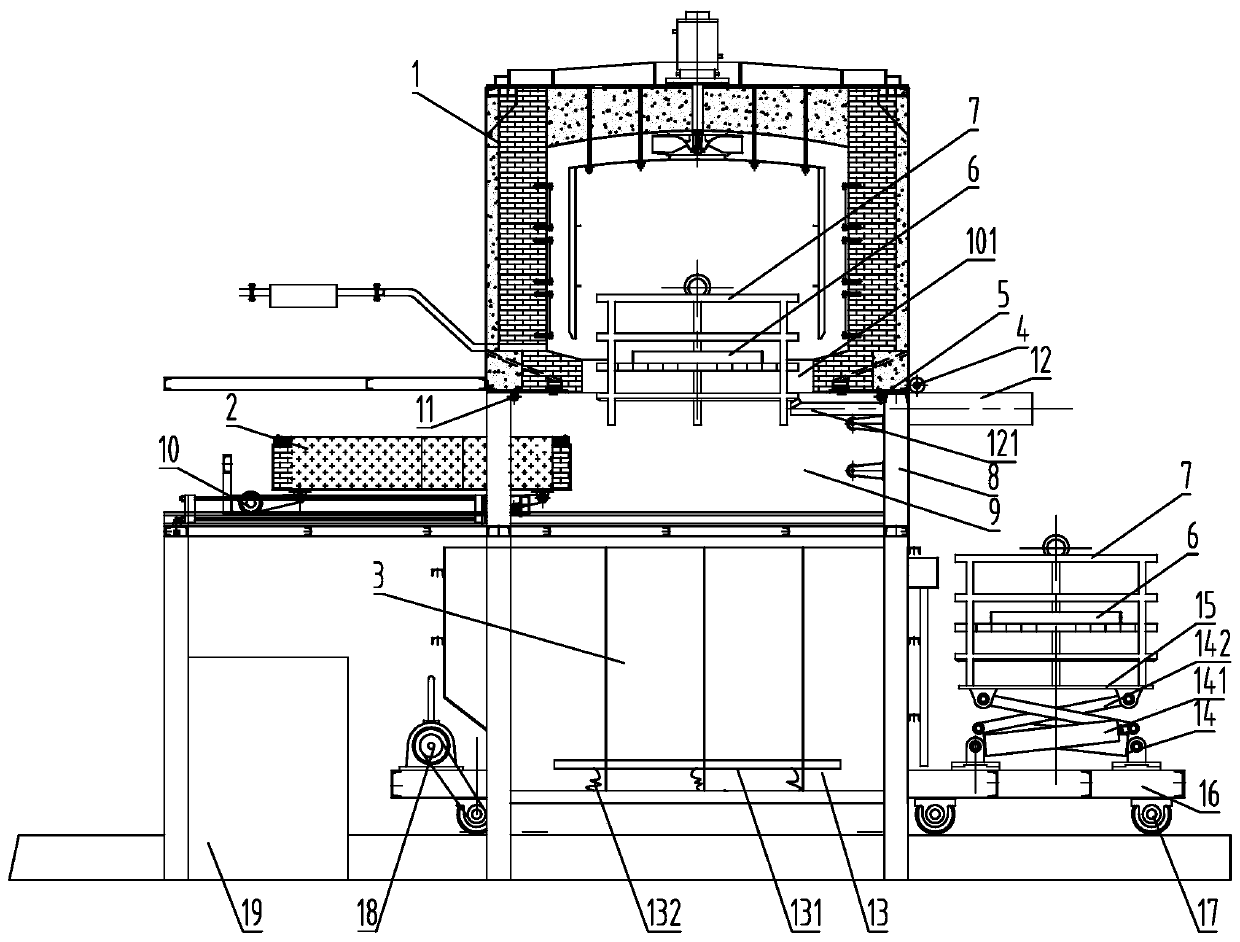
[0036] The specific implementation manners of the present invention will be described in further detail below in conjunction with the accompanying drawings. These embodiments are only used to illustrate the present invention, not to limit the present invention.

[0037] In the description of the present invention, it should be noted that the terms "center", "longitudinal", "transverse", "upper", "lower", "front", "rear", "left", "right", " The orientations or positional relationships indicated by "vertical", "horizontal", "top", "bottom", "inner", "outer", etc. are based on the orientation or positional relationships shown in the drawings, and are only for the convenience of describing the present invention and simplifying Describes, but does not indicate or imply that the device or element referred to must have a specific orientation, be constructed in a specific orientation, and operate in a specific orientation, and therefore should not be construed as limiting the inventio...


PUM


Abstract

The invention relates to the technical field of solid melting treatment equipment, in particular to solid melting furnace equipment. The solid melting furnace equipment comprises a furnace body, a furnace cover, a water tank, a sealing curtain, and a first air blowing pipe, wherein an opening is formed in the lower end of the furnace body; the furnace cover is used for sealing or opening the opening; the water tank is arranged below the furnace body, and the upper end of the water tank is opened to be opposite to the opening at intervals; the sealing curtain is arranged at the periphery of theopening and is used for connecting the furnace body and the water tank to form a sealed space; and the first air blowing pipe is arranged on one side, close to the opening, of the sealing curtain, and is used for introducing shielding gas into the sealed space. The invention further relates to a solid melting method. The solid melting method comprise the steps that the solid melting furnace equipment is adopted; before a set heat preservation time is reached, a sealing curtain is used for connecting the furnace body and the water tank to form the sealed space; the sealed space is filled withthe shielding gas by the first air blowing pipe; after the set heat preservation time is reached, the furnace cover is moved, so that the opening is opened; and a material frame falls into the water tank from the opening through the sealed space. The time that a solid-melting material is discharged out of a furnace and enters water can be reduced, the situation that the material can rapidly enterthe water after the material is discharged out of the furnace is realized, and no oxidation is generated.

Description

technical field [0001] The invention relates to the technical field of solid melting treatment equipment, in particular to a solid melting furnace equipment and a solid melting method. Background technique [0002] The mainstream solid solution heat treatment of copper or special alloy is to heat in the furnace body of the solid solution furnace and then take it out of the furnace and enter water for cooling. The furnace body is evacuated and filled with protective gas, so the solid solution material will not be oxidized in the furnace body, but the solid solution material will be oxidized when it is directly exposed to the air after it is released from the furnace and before it falls into the water. Usually, the time for the solid solution material to come out of the furnace and enter the water is 30 seconds to 180 seconds. The longer the solid solution material is exposed to the air, the more serious its surface oxidation is, and the longer the water entry time will cause...

Claims


Application Information

Patent Timeline
Patent Type & Authority Applications(China)
IPC IPC(8): C21D9/00C21D1/74C21D1/63
CPCC21D1/63C21D1/74C21D9/0062
Inventor 苏华光张永甲李冬俊
Owner SHANGHAI ELECTRIC CABLE RES INST
Why Eureka
Try Eureka