
Cable vibraguard

a vibraguard and cable technology, applied in the field of cable guards, can solve the problems of cable wear, noise generation upon bowstring release, and cable wear, and achieve the effects of reducing hand shock and vibration, avoiding arm fatigue, and being economical to produce and maintain

Inactive Publication Date: 2005-05-10
VIBRAGUARD
View PDF7 Cites 15 Cited by
  • Summary
  • Abstract
  • Description
  • Claims
  • Application Information

AI Technical Summary

Benefits of technology

[0023]It is yet another object of the present invention to provide a cable guard that decreases the noise generated during use as to not alert or frighten game birds and animals.
[0038]When the bowstring is released, the biasing means returns to its relaxed (uncompressed) position and the first and second cables are compelled to stop vibrating by the movement of the biasing means returning to the original position, thereby decreasing the amount of vibration noise produced by the vibrating of the first and the second cable. In addition, a bumper may optionally be attached to the cable guard that may come into contact with the bow strings after the arrow has been shot. The bumper may, at least partially, function to cause the strings to stop vibrating through this contact.

Problems solved by technology

A problem presented by compound bows is that noise is generated upon releasing the bowstring to propel the arrow.
This rubbing causes frictional forces that may produce cable wear and create noise which may alert game birds and animals.
Unfortunately, the rod length can be a potential distraction to the archer when the arrow is being shot.
Another problem presented by the rod of the prior art is that most archers do not remove the cable guard from their bow for transport, and because many forms of transportation require bows to be cased for transport, the use of such cable guards requires substantial storage area and larger bow cases.
Another problem presented by a conventional compound bow is that a considerable amount of energy stored in bow limb is wasted by propelling the bow limb forward when the drawn bowstring is released.
Another problem presented by a conventional compound bow is that the crossing cables are located in the point of view of the archer, thus diminishing the visibility of the archer.

Method used


Image

  • Cable vibraguard
  • Cable vibraguard
  • Cable vibraguard

Examples


Embodiment Construction

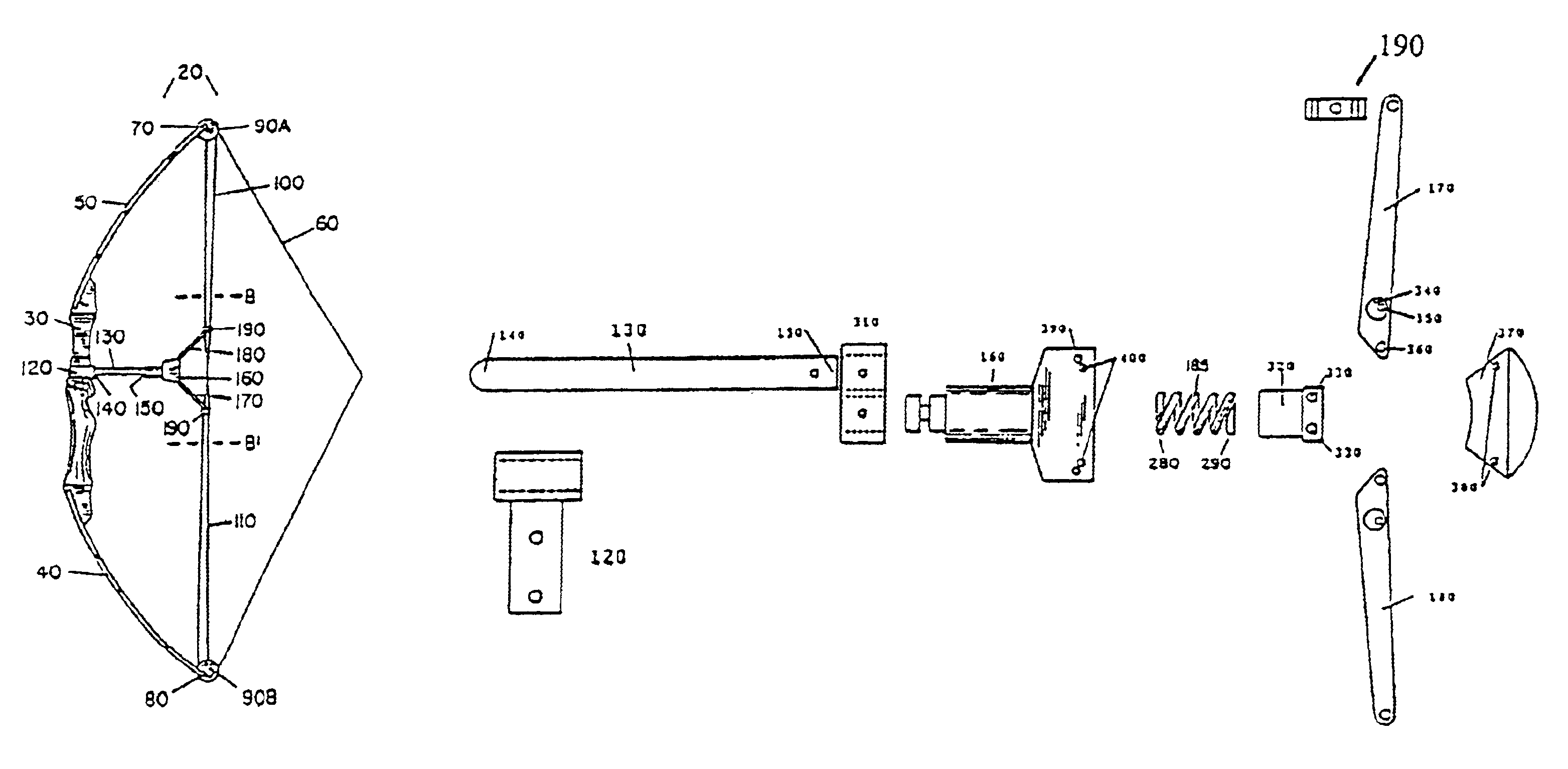
[0057]FIG. 1 is a side view illustrating the cable guard 10 of the present invention attached to a compound bow in a rest position. The cable guard 10 is used with a conventional compound bow 20 having a bow handle 30 and a pair of bow limbs 40, 50. The first bow limb 40 and the second bow limb 50 are oppositely positioned in bow handle 30. Bowstring 60 spans between a first bow tip 70 and a second bow tip 80. The bowstring 60 then continues and extends over the pulleys 90A, 90B positioned at or proximate to each of the bow tips 70, 80, and then the two ends of the bowstring 60, designated first cable end 100 and second cable end 110, cross to the opposite limb at which point they are attached to define a compound bow 20.

[0058]FIG. 2 is a side view illustrating the cable guard of the present invention attached to a compound bow in a drawn position.

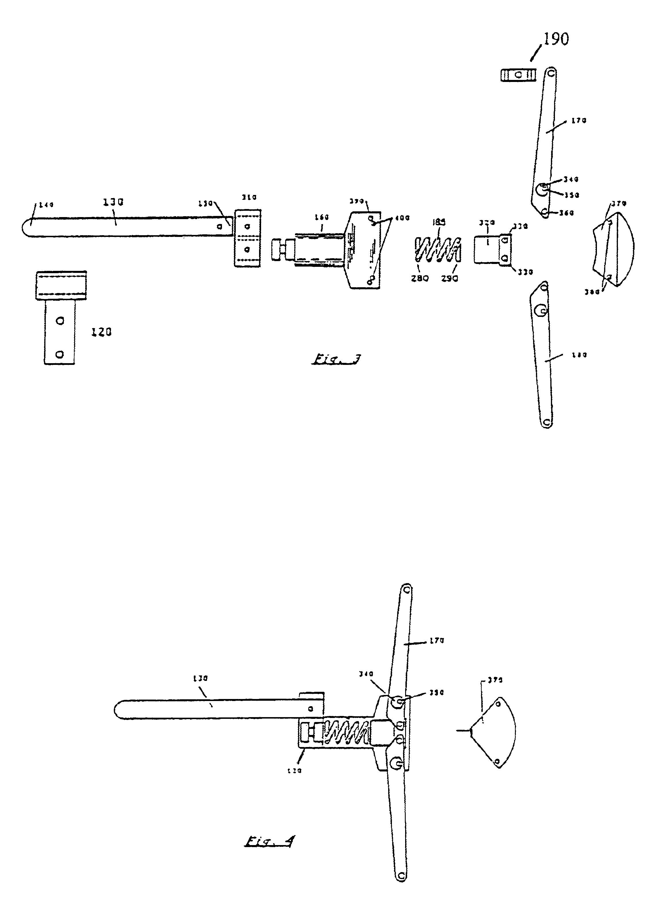
[0059]FIG. 3 is a partial section taken along line A-A1 on FIG. 1 and provides greater detail of an embodiment of the cable guard 10 of t...


PUM


Abstract

The present invention concerns a cable guard for use with a compound bow, the compound bow having a handle portion and a pair of opposite bow limbs, a first and a second cable which cross one another in extending between opposite bow limbs and a bowstring, the cable guard includes: a rod having a first end and a second end, wherein the first end of the rod is attached to the handle portion of the compound bow; a housing disposed at the second end of the rod; a pair of swing arms extending opposite to each other and outwardly from the housing in the direction of the bow limbs, the pair of swing arms pivotally connected about a point near one end of the housing; a biasing device in contact with the other end of the housing and the second end of the rod; and wherein when the bowstring is drawn to a draw position, the swing arms move in the direction of the bowstring moving the housing in the direction of the handle compressing the biasing device.

Description

[0001]This patent application is a continuation-in-part of U.S. patent application Ser. No. 10 / 105,899, filed Mar. 25, 2002 now U.S. Pat. No. 6,708,684, allowed on Aug. 22, 2003.FIELD OF THE INVENTION[0002]This invention relates to a cable guard for a compound bow. More specifically, a cable guard that reduces noise generated by the vibration of the cables, and at the same time, helps increase the speed of the arrow.BACKGROUND OF THE INVENTION[0003]In the sport of archery, the basic configuration and operation of compound bows are generally known as they have been in use for a long time. Compound bows are used a great deal in hunting because they provide several advantages over the simpler non-compound varieties.[0004]Compound archery bows include tension cables and a bowstring that are connected between upper and lower bow limbs. It is customary to dispose the bowstring and the tension cables relatively close together, proximate the vertical centerline of the bow, in order to minim...

Claims


Application Information

Patent Timeline
IPC IPC(8): F41B5/00F41B5/20F41B5/10
CPCF41B5/1426F41B5/10
Inventor CHATTIN, JESSE R.
Owner VIBRAGUARD
Learn More