
Distal component for wrist prosthesis

a technology of wrist prosthesis and distal component, which is applied in the field of wrist prosthesis, can solve the problems of inability to pass torsional loads onto soft tissue, design failure, and inability to meet the needs of patients,

Inactive Publication Date: 2005-05-10
DEPUY PROD INC
View PDF19 Cites 134 Cited by
  • Summary
  • Abstract
  • Description
  • Claims
  • Application Information

AI Technical Summary

Benefits of technology

[0009]The subject invention is a distal component for a wrist prosthesis. Particularly, the subject invention is a distal component for a wrist prosthesis that utilizes fixation within the carpus complex, incorporates features that improve the probability of intercarpal fusion, and allows modularity of articulating components.
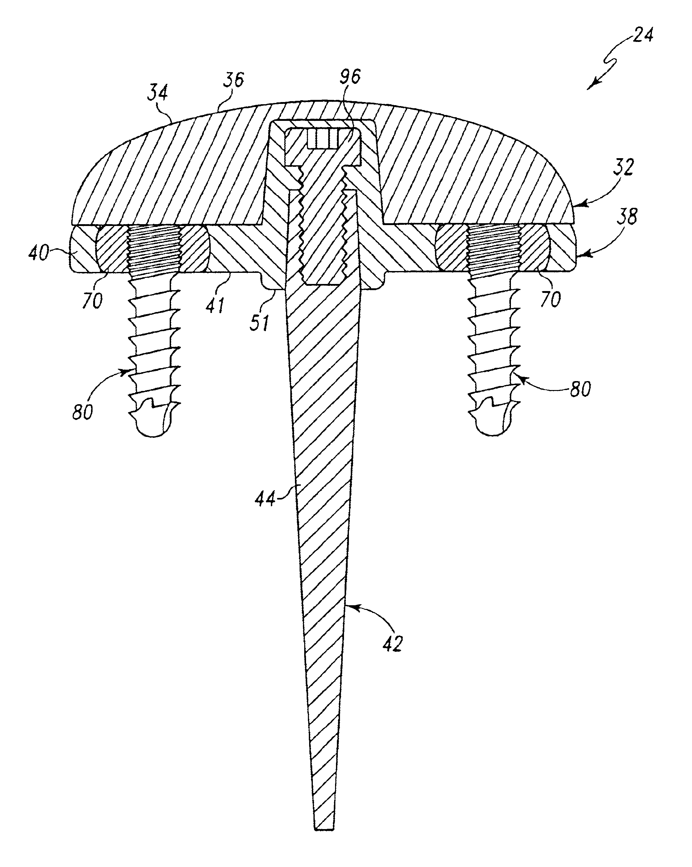
[0016]The attachment of the articulating head to the fixation plate can exist in two embodiments. In one embodiment, the hole and boss are precisely machined so that the mating surfaces of the head and plate firmly engage, and provide a solid construct in vivo. In a second embodiment, the hole and boss are precisely machine such that the distal surface of the head bottoms out on the proximal surface of the plate. In the condition where these surfaces mate, the hole and boss do not engage, allowing rotation about the axis of the hole of the articulating head. Further, the modularity of the articulation heads allows options for offset rotation centers, varying head heights, varying degrees of articular laxity, materials, and / or motion.

Problems solved by technology

While various wrist prosthetics have been developed and patented, they all suffer from loosening of one of the two components of the wrist prosthetic.
The torsional loads cannot be passed onto soft tissue due to the constrained design of prostheses.
Such designs have not been well received due to the inherently weak bone stock available for the metacarpal component in typical wrist implant patients.
Also, some designs fail because there is an effort to obtain greater fixation, when motion is still present.
Another problem with wrist prosthetics is loosening of the distal implant component after implantation.
This solution, however, has not produced superior results to the primary implant outcome.

Method used


Image

  • Distal component for wrist prosthesis
  • Distal component for wrist prosthesis
  • Distal component for wrist prosthesis

Examples


Embodiment Construction

[0035]While the invention is susceptible to various modifications and alternative forms, specific embodiments thereof have been shown by way of example in the drawings and will herein by described in detail. It should be understood, however, that there is no intent to limit the invention to the particular forms disclosed, but on the contrary, the intention is to cover all modifications, equivalents, and alternatives falling within the spirit and scope of the invention as defined by the appended claims.

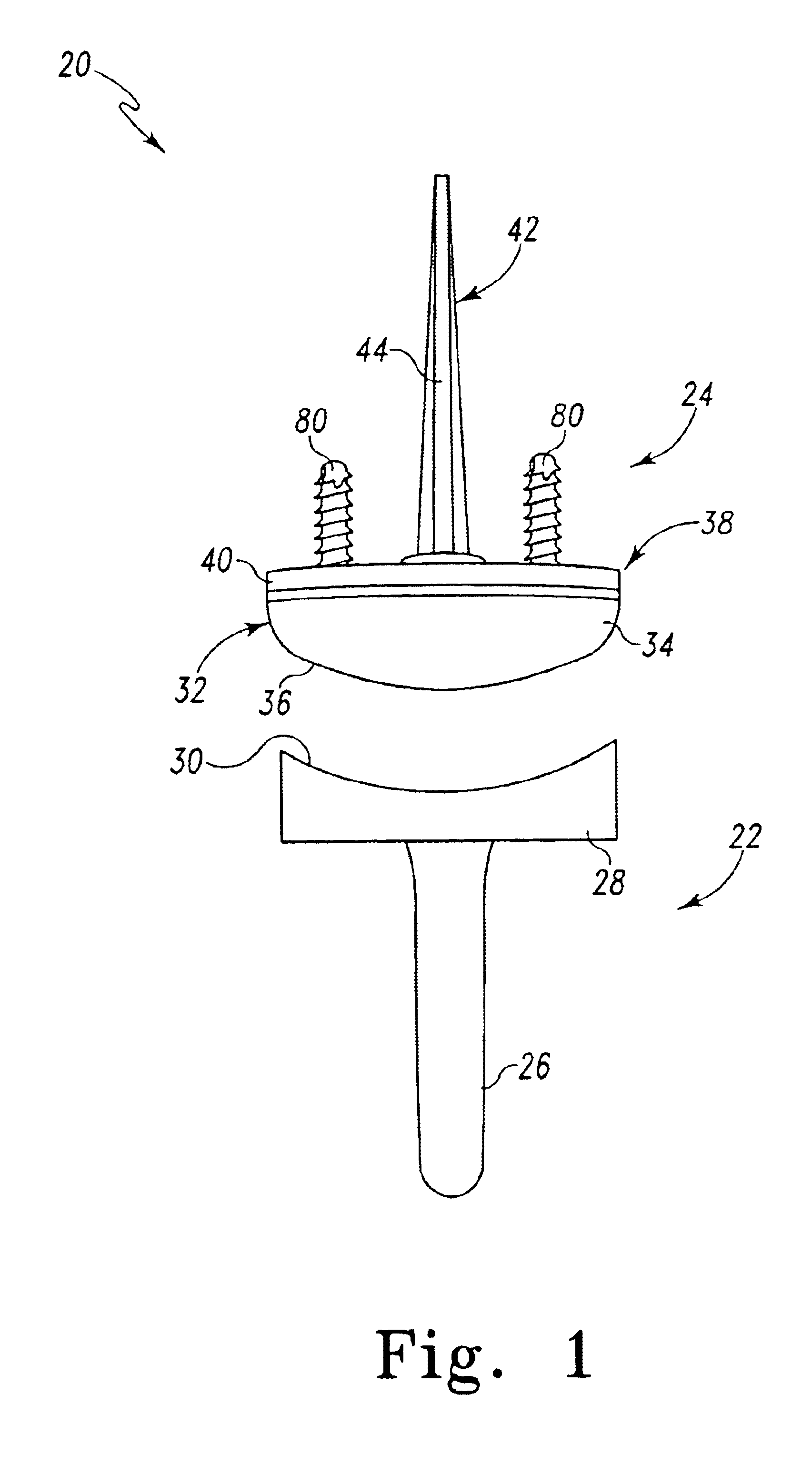
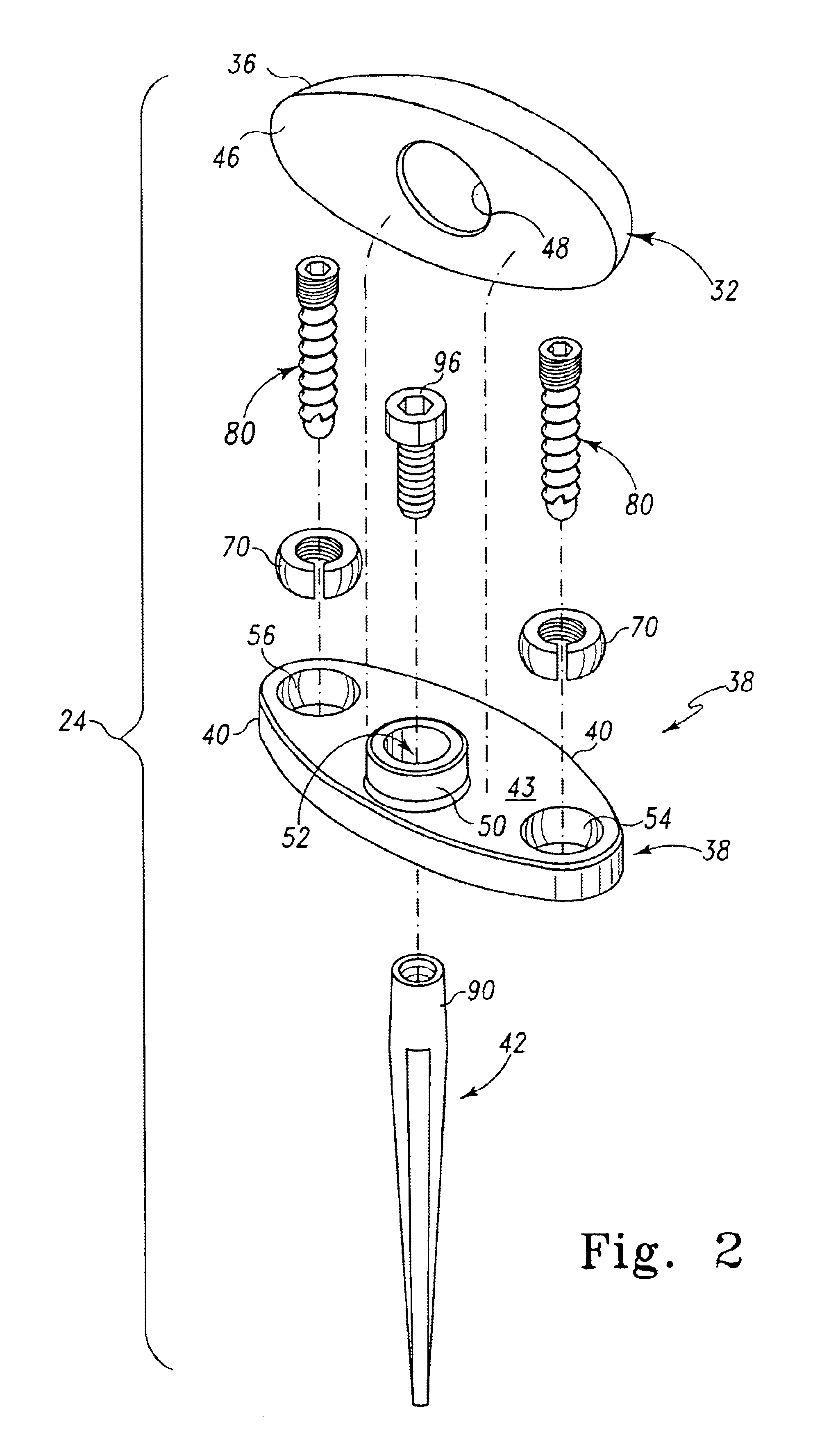
[0036]Referring now to FIG. 1 there is shown an exemplary embodiment of a wrist prosthesis in accordance with the principles of the subject invention, the wrist prosthesis generally designated 20. The wrist prosthesis 20 includes a radial or proximal component generally designated 22 and a carpal or distal component, generally designated 24. The proximal component 22 is configured, adapted and / or operative to be implanted into a radius of a patient. The distal component 24 is configure...


PUM


Abstract

A distal component for a wrist prosthesis that utilizes fixation within the carpus complex, incorporates features that improve the probability of intercarpal fusion and allows modularity of articulating components. In one form, the subject invention includes an ovoid fixation plate having three holes and a boss. The three holes allow attachment of stems and / or screws distally for fixation in the carpus. The boss projects proximally from the plate, and serves as an attachment point for the articulating head. Modularity of the fixation and articulating components allow a surgeon many options for optimizing fixation distally, and articulation proximally. The proximal head of the distal component is designed to articulate with existing radial components. Since the proximal head of the distal component is modular, however, the head can be redesigned to accommodate later design changes in proximal components.

Description

[0001]This application claims the benefit of U.S. Provisional Application Ser. No. 60 / 368,740, filed Mar. 29, 2002.TECHNICAL FIELD OF THE INVENTION[0002]The present invention relates to wrist prostheses particularly for total wrist arthroplasty.BACKGROUND OF THE INVENTION[0003]A normal human wrist may be considered as comprising three sets of bones: the distal forearm, constituting the distal portion of the radius and the ulna; the carpals, constituting eight bones divided into two rows, i.e. the proximal bones (scaphoid, lunate, triquetrum, and pisiform) and the distal bones (trapezium, trapezoid, capitate, and hamate), that are most closely associated with the motion of the wrist; and the metacarpals, constituting the distal segments (i.e. thumb and four fingers).[0004]The wrist is commonly considered a biaxial joint, meaning that there are two principle movements of the wrist, namely an extension-flexion movement and a radial / ulnar movement. Although the wrist has no intrinsic me...

Claims


Application Information

Patent Timeline
IPC IPC(8): A61F2/42A61B17/80A61F2/00A61F2/30
CPCA61F2/4261A61B17/8047A61F2310/00029A61F2002/30125A61F2002/3021A61F2002/30253A61F2002/30332A61F2002/30344A61F2002/30405A61F2002/30408A61F2002/30474A61F2002/30497A61F2002/30507A61F2002/30604A61F2002/30774A61F2002/30785A61F2002/3079A61F2002/30794A61F2002/30797A61F2002/30827A61F2002/30878A61F2002/4264A61F2220/0025A61F2220/0033A61F2230/0008A61F2230/0067A61F2230/0076A61F2310/00011A61F2002/30339A61F2002/30495
Inventor BALL, ROBERT J.TRAIL, IAN A.PASCAUD, RAPHAELBECKENBAUGH, ROBERTGEISSLER, WILLIAM
Owner DEPUY PROD INC
Learn More