Ceramic honeycomb filter and its structure

a honeycomb filter and honeycomb technology, applied in the field of honeycomb filters, can solve the problems of low breakage resistance of the filter, increase the pressure loss, and reduce the strength of the partition wall, so as to reduce the pressure loss and reduce the breakage resistance

Inactive Publication Date: 2005-05-10
HITACHI METALS LTD
View PDF45 Cites 39 Cited by
  • Summary
  • Abstract
  • Description
  • Claims
  • Application Information

AI Technical Summary

Benefits of technology

[0016]Accordingly, an object of the present invention is to provide a ceramic honeycomb filter having small pressure loss free from cracking due to thermal stress and thermal shock at the time of regenerating the filter, and a ceramic honeycomb structure used therefor.
[0017]Another object of the present invention is to provide a ceramic honeycomb structure, in which cracking is less likely to propagate continuously in a diagonal direction of cells along partition wall intersections on which stress is concentrated.
[0018]A further object of the present invention is to provide a high-strength ceramic honeycomb structure capable of being used as a particulates-capturing filter stably for a long period of time even with porosity of 50% or more.DISCLOSURE OF THE INVENTION
[0019]As the result of intensive research on partition walls and sealers of honeycomb filters in view of the above objects, the inventors have found that by adjusting the porosity, pore shapes and seal depth of sealers combined with partition walls, pressure loss can be reduced without lowering breakage resistance. The present invention has been completed based on this finding.

Problems solved by technology

Though the pressure loss can be reduced by increasing the porosity and pore size of partition walls or by decreasing exhaust gas resistance, larger porosity and pore size leads to lower strength in the partition walls, resulting in low breakage resistance of the filter.
Further, sealers formed at both ends of the honeycomb filter not only increases the pressure loss, but also lowers the thermal shock resistance.
It is thus difficult to satisfy both of the requirements of pressure loss and breakage resistance.
However, the ceramic honeycomb structure of JP 7-332064 A, as described in its Examples, has as small porosity as 45% and thus large pressure loss of a ceramic honeycomb filter.
Because it does not have pores in sealers on an inlet side while it has pores in sealers on an exit side, an exhaust gas cannot pass through the sealers on the inlet side, resulting in insufficient effect of reducing the pressure loss.
However, when the seal depth of the honeycomb filter is nonuniform, there is only a small effective area as a filter in portions having large seal depth, resulting in large pressure loss.
Also, with the nonuniform seal depth, filter areas differ from product to product, causing the problem that the resultant honeycomb filters do not have constant quality.
Further, there is weak adhesion strength between the sealers and the partition walls in portions having small seal depth, the sealers are likely to peel off by the pressure of an exhaust gas or thermal shock, etc.
Accordingly, when used for catalyst converters and particulates-capturing filters, it is likely to suffer from cracking 13 in partition wall intersections by thermal shock or stress as shown in FIG. 6, resulting in breakage in a diagonal direction of cells.
However, because the partition walls are not thick in a core portion of the ceramic honeycomb structure, the partition wall intersections have uniform strength, so that cracking generated in the partition wall intersections continuously propagate through the core portion.
However, because the strength of the partition wall intersections is uniform throughout the ceramic honeycomb structure, cracking generated by thermal shock or stress continuously propagates along the partition wall intersections.
However, because these porous ceramic honeycomb filters have high porosity, they inevitably have low strength.
Therefore, stress concentration is likely to occur in the pores, causing decrease in the strength of the ceramic honeycomb structure.
Thus, when it is used for particulates-capturing filters for exhaust gases from diesel engines, it is likely to be broken by thermal stress and shock, a mechanical fastening force at the time of assembling, vibration, etc.

Method used


Image

  • Ceramic honeycomb filter and its structure
  • Ceramic honeycomb filter and its structure
  • Ceramic honeycomb filter and its structure

Examples


first embodiment

[1] First Embodiment

[0050]In the first embodiment, the ceramic honeycomb structure has a porosity of 50-80%, relatively large-diameter pores, specifically pores having cross section areas of 1,000μm2 or more in partition walls, contain those having substantially circular cross sections. This reduces the percentage of the number of pores having acute corners, making it unlikely that stress concentration occurs in the corners of pores, and thus resulting in improvement in the strength of the ceramic honeycomb structure. The term “pores are substantially circular” in partition walls means that the roundness represented by the formula of length of circumference×length of circumference / (4π×area of pore) is within a range of 1-10. In the case of a circle, the roundness is 1, and the roundness becomes larger as the cross section shape of a pore becomes deviated from a circle.

[0051]When the porosity is less than 50%, the ceramic honeycomb structure has a large pressure loss when used as a d...

second embodiment

[2] Second Embodiment

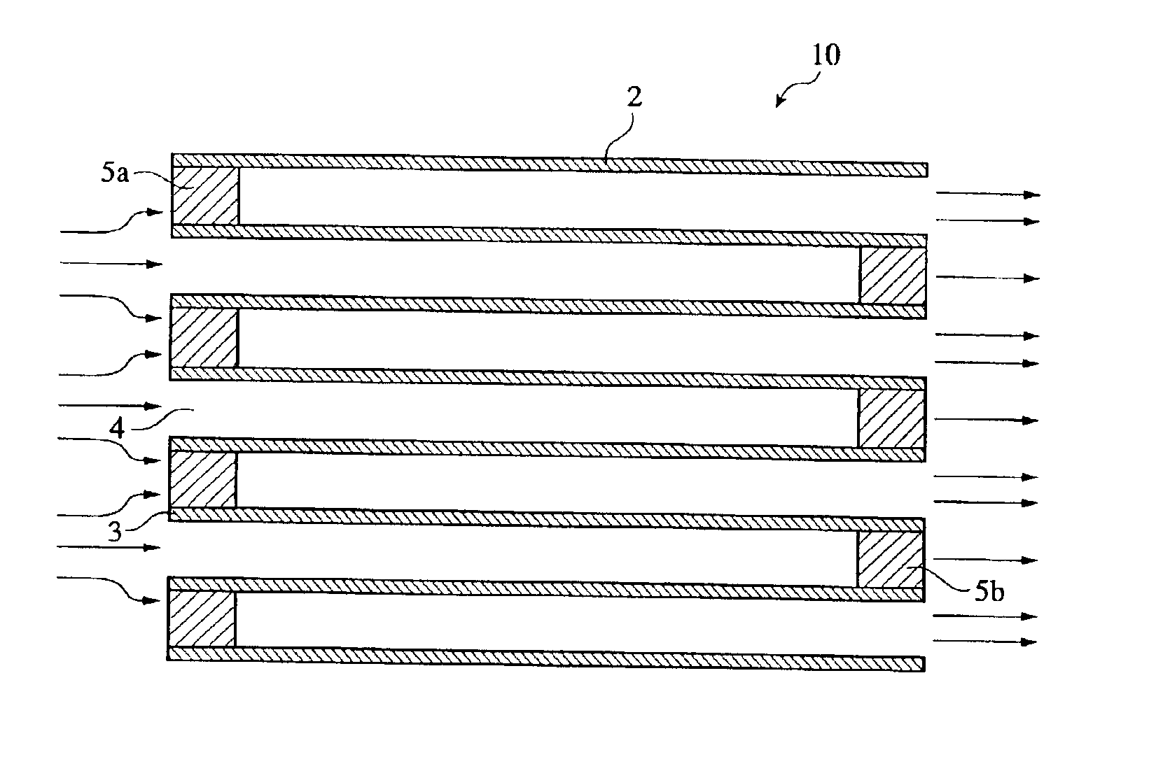
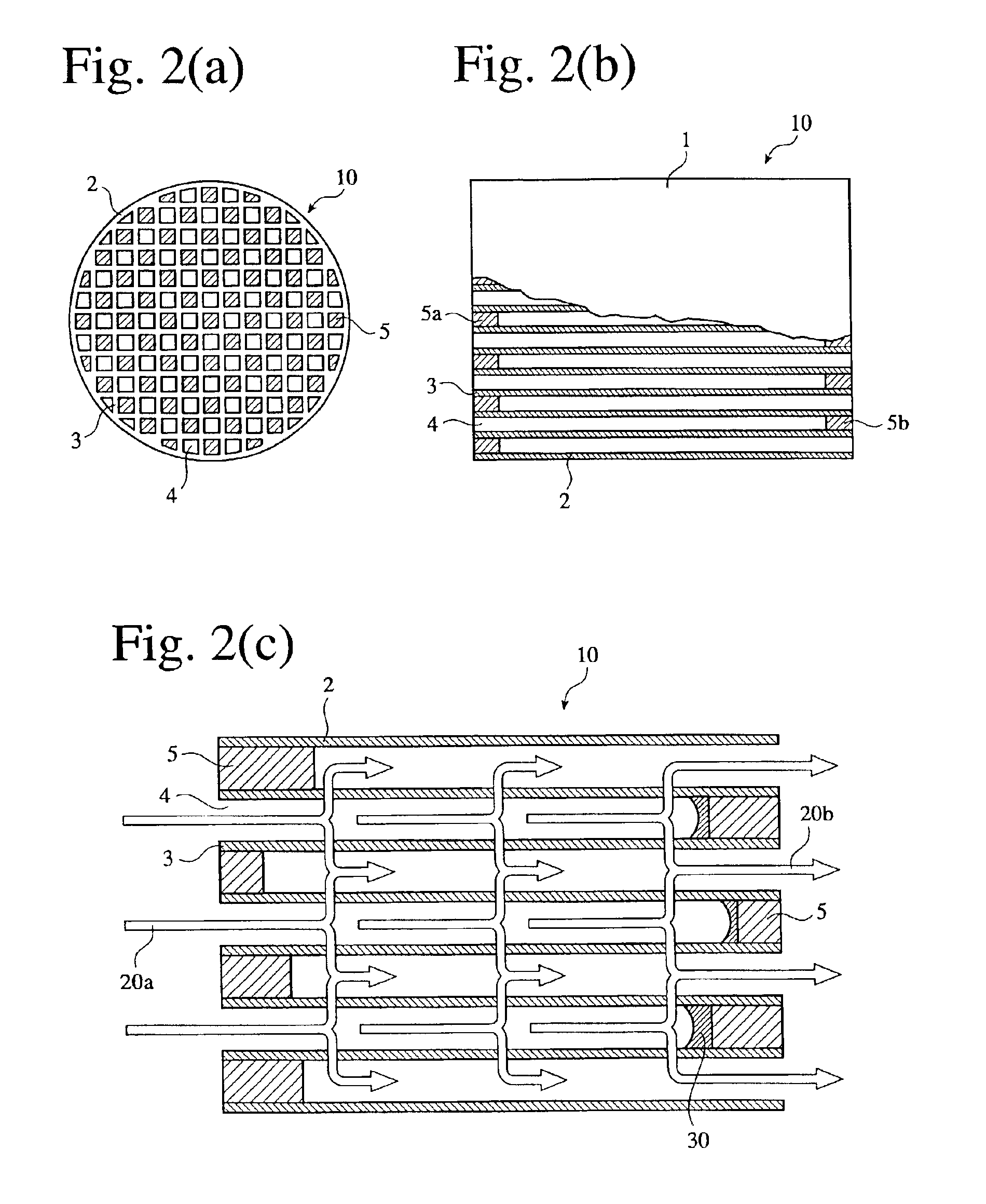
[0057]In the second embodiment, the partition walls of the ceramic honeycomb filter have thickness of 0.1-0.5 mm and a porosity of 50-80%, the porosity of sealers is larger than that of partition walls, and the seal depth is 3-15 mm. This structure can satisfy two contradictory requirements of a low pressure loss and an excellent breakage resistance. Specifically, because partition walls have thickness of 0.1-0.5 mm and as high porosity as 50-80%, the exhaust gas passes through the partition walls with low resistance (pressure loss). Also, with the porosity of sealers larger than that of partition walls and with the seal depth of 3-15 mm, part of the exhaust gas passes through the sealers, resulting in decrease in pressure loss. Further, because the sealers have a small thermal capacity per a unit area, the sealers is unlikely to suffer from cracking even with a thermal shock.

[0058]Specifically, the porosity of sealers is larger than that of partition walls pref...

third embodiment

[3] Third Embodiment

[0066]The partition walls of the ceramic honeycomb structure in the third embodiment have nonuniform thickness. As shown in FIGS. 5(a) to5(c), for instance, the partition walls 3a, 3b of the ceramic honeycomb structure 1 have different thickness in a transverse cross section. Because the partition walls 3 has nonuniform thickness, partition wall intersections 3c have different strength from cell to cell, not constant in the ceramic honeycomb structure. Because no partition wall intersections 3c having substantially the same strength exist continuously, it is possible to prevent a phenomenon that cracking propagates continuously along the partition wall intersections 3c by thermal shock or stress, so that the ceramic honeycomb structure is broken in a diagonal direction of cells. Thus, this ceramic honeycomb structure has excellent thermal shock resistance. Incidentally, because the partition wall intersections 3c shown in FIG. 5(c) have curved surfaces, it is adv...


PUM

PropertyMeasurementUnit
porosityaaaaaaaaaa
depthaaaaaaaaaa
areasaaaaaaaaaa

Abstract

A ceramic honeycomb filter comprising a ceramic honeycomb structure having porous partition walls defining a plurality of flow paths for flowing an exhaust gas through the porous partition walls to remove particulates from the exhaust gas, wherein one end of each flow path is provided with a sealer, such that sealers of the flow paths in an inlet and an outlet of the ceramic honeycomb structure in a desired pattern; wherein the partition walls have thickness of 0.1-0.5 mm and a porosity of 50-80%; wherein the porosity of the sealers is larger than that of partition walls; and wherein the depth of the sealers is 3-15 mm.

Description

FIELD OF THE INVENTION[0001]The present invention relates to a ceramic honeycomb filter for capturing particulates in exhaust gases of automobiles, particularly those from diesel engines, and a ceramic honeycomb structure used therefor.BACKGROUND OF THE INVENTION[0002]To remove carbon-based particulates from exhaust gases emitted from diesel engines, ceramic honeycomb filters comprising porous ceramic honeycomb structures with both ends alternately sealed are used.[0003]As shown in FIG. 1, a ceramic honeycomb structure 1 is substantially cylindrical (including an elliptic cross section) with partition walls 3 inside an outer wall 2 and a large number of cells (flow paths) 4 encircled thereby. As shown in FIG. 2(b), both ends of the flow paths 4 are alternately sealed by sealers 5a, 5b. [0004]The cleaning an exhaust gas by a honeycomb filter 10 is carried out as shown in FIG. 2(c). The exhaust gas 20a flows into the flow paths 4 of the honeycomb filter 10, passes through pores in the...

Claims


Application Information

Patent Timeline
Patent Type & Authority Patents(United States)
IPC IPC(8): B01J35/00B01J35/04C04B35/584C04B35/10C04B35/18C04B35/185C04B35/19C04B35/565F01N3/022B01D46/24B28B11/00C04B38/00
CPCB01D46/244B01D46/2459B01D46/247B01D46/2474B01J35/04B28B11/006B28B11/007C04B35/10C04B35/185C04B35/19C04B35/195C04B35/565C04B35/584C04B38/0009F01N3/0222B01D46/2429C04B38/0012B01D46/2425Y10T428/24149B01D46/2451B01D46/2466B01D2046/2433B01D2046/2437B01D2046/2496C04B2111/0081C04B2235/3203C04B2235/77C04B2235/96C04B2235/9607F01N2330/06F01N2330/30Y10T428/24157Y02T10/20Y10T428/249975Y10T428/249981Y10T428/249953Y02T10/12B01D46/2498B01D46/24492B01D46/24491B01D46/2482B01D46/249
Inventor SUWABE, HIROHISAOKAZAKI, SHUNJITOKUDOME, OSAMUOTSUBO, YASUHIKO
Owner HITACHI METALS LTD
Why Eureka
Try Eureka