
Method and apparatus for improving video quality

Inactive Publication Date: 2005-05-10
LG ELECTRONICS INC
View PDF6 Cites 50 Cited by
  • Summary
  • Abstract
  • Description
  • Claims
  • Application Information

AI Technical Summary

Benefits of technology

[0017]An object of the present invention is to provide a simple-structured video restoring apparatus and method thereof.

Problems solved by technology

Yet, the interpolating method of U.S. Pat. No. 4,876,596 is realized by a simple hardware but fails to prevent a degraded quality of the video.
The interpolation method disclosed in U.S. Pat. No. 5,596,371 enables to improve an image quality after interpolation, but utilizes complicated hardware.
Yet, the interpolation method disclosed in U.S. Pat. No. 5,689,301 fails to detect a motion of an object moving instantly or at a specific speed in a system detecting a motion between frames.
Moreover, the interpolation method disclosed in U.S. Pat. No. 5,689,301, in case of detecting a motion between simple frames, results in an excessive motion detection so as to reduce an image resolution after interpolation.
Therefore, the entire image quality is degraded.
Therefore, the entire structure of the hardware gets complicated as well as the manufacturing cost of the corresponding circuit is increased.
Unfortunately, the interpolation methods according to the related arts realized by simple hardware degrade an image quality after interpolation.
Moreover, the interpolation methods according to the related arts require complicated structure of hardware to improve an image quality after interpolation.
Furthermore, the interpolation methods according to the related arts require a plurality of memory devices or complicated processing procedures for detecting the motion of the object precisely, whereby the entire structure of the hardware gets complicated as well as the manufacturing cost of the corresponding circuit is increased.

Method used


Image

  • Method and apparatus for improving video quality
  • Method and apparatus for improving video quality
  • Method and apparatus for improving video quality

Examples


Embodiment Construction

[0032]Reference will now be made in detail to the preferred embodiments of the present invention, examples of which are illustrated in the accompanying drawings.

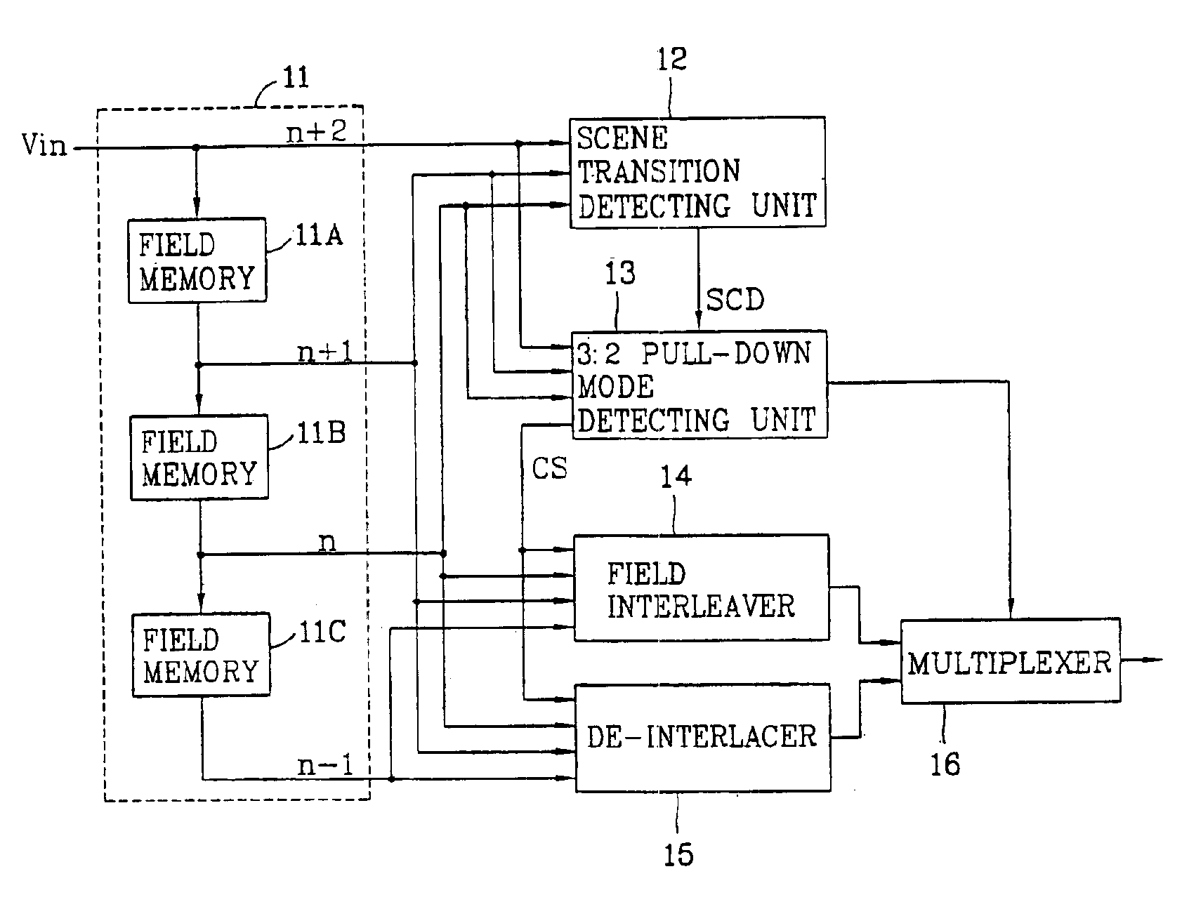
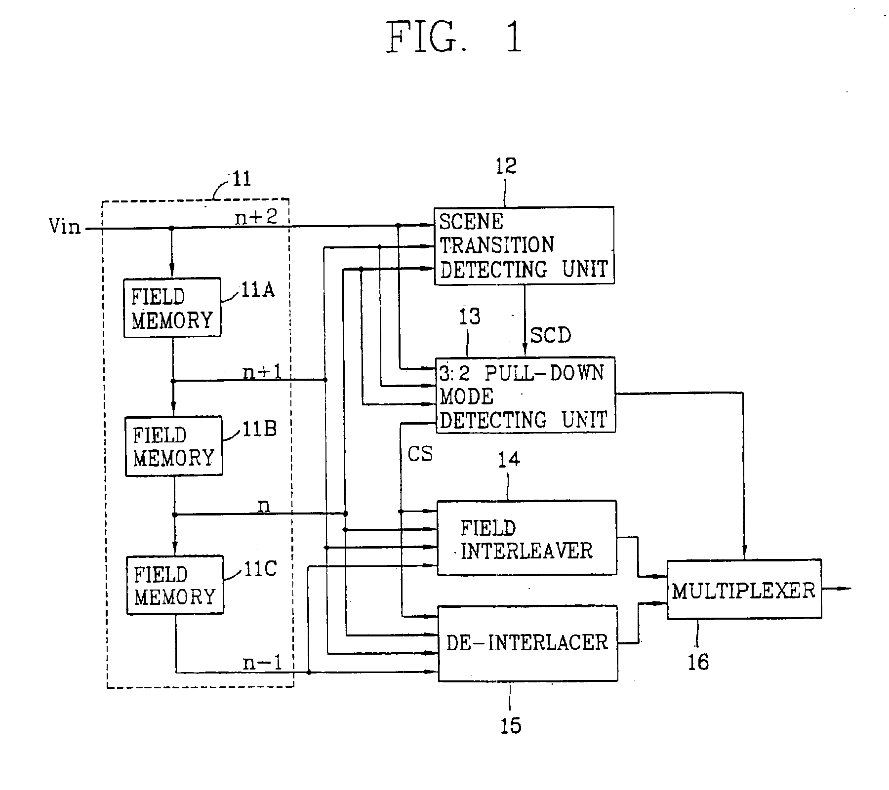
[0033]FIG. 1 illustrates a block diagram of a video restoring apparatus according to the present invention.

[0034]Referring to FIG. 1, a field data providing unit 11 provides data of previous fields n and n−1, a current field n+1, and a future field n+2 by constructing three field memories 11A to 11C. A scene transition detecting unit 12 detects a motion between the fields adjacent to the current field n+1 by receiving the field data from the field data providing unit 11. On the basis of the detected motion, the scene transition detecting unit 12 outputs a scene transition detecting signal by identifying whether a scene of an inputted image sequence is changed on the basis of the detected motion. A 3:2 pull-down mode detecting unit 13 detects whether a 3:2 pull-down mode exists in the inputted image sequence by receiving the ...


PUM


Abstract

Disclosed is a video restoring apparatus and method thereof enabling to improve a video mode by interpolating field data. The present invention includes the steps of: identifying whether a scene on an image sequence is changed by receiving field data; detecting whether a 3:2 pull-down mode exists in the image sequence; generating a first interpolated frame by interleaving a field to be interpolated and adjacent fields each other when there is the 3:2 pull-down mode; generating a second interpolated frame by de-interlacing the field to be interpolated and the adjacent fields each other when there is not the 3:2 pull-down mode, and selectively outputting one of the first and second interpolated frames.

Description

CROSS REFERENCE TO RELATED ART[0001]This application claims the benefit of Korean Patent Application No. 2000-73724, filed on Dec. 6, 2000, the contents of which is hereby incorporated by reference in its entirety.BACKGROUND OF THE INVENTION[0002]1. Field of the Invention[0003]The present invention relates to a video restoring apparatus and method thereof enabling to improve a video quality, and more particularly, to a video restoring apparatus and method thereof enabling to improve a video quality by interpolating field data.[0004]2. Background of the Related Art[0005]Generally a computer monitor plays a video by a progressive scan mode, while a general television plays a video by an interlacing mode. In this case, the interlacing is a method that divides a frame (TV screen of National Television System Committee, NTSC, requires 30 frames per second) into two fields consisting of odd field and even field and then generates one frame by sequentially scanning the two fields. And, the...

Claims


Application Information

Patent Timeline
IPC IPC(8): H04N7/01
CPCH04N7/0135H04N7/0112H04N7/01
Inventor SHIN, CHANG YONGHAN, DONG IL
Owner LG ELECTRONICS INC
Learn More