Frequency offset correction system and correction method

a frequency offset and correction system technology, applied in phase-modulated carrier systems, amplitude demodulation, digital transmission, etc., can solve the problem of increasing the influence of the frequency offset error caused by the integration operation, and increasing the truncation error of the frequency offset. the effect of increasing the precision of the frequency offset correction

Inactive Publication Date: 2005-05-10
NEC CORP
View PDF7 Cites 3 Cited by
  • Summary
  • Abstract
  • Description
  • Claims
  • Application Information

AI Technical Summary

Benefits of technology

[0014]It is an object of the present invention to provide a frequency offset cor...

Problems solved by technology

In the conventional frequency offset correction method, when the channel bit rate of data of I-Channel is higher than that of pilot signal data of Q-Channel, e.g., the truncation error of the frequency offset in obtaining a phase shift Δθ per bit increases.
Thus, the number of phase shifts Δθ...

Method used


Image

  • Frequency offset correction system and correction method
  • Frequency offset correction system and correction method
  • Frequency offset correction system and correction method

Examples


Embodiment Construction

[0022]The present invention will be described in detail below with reference to the accompanying drawings.

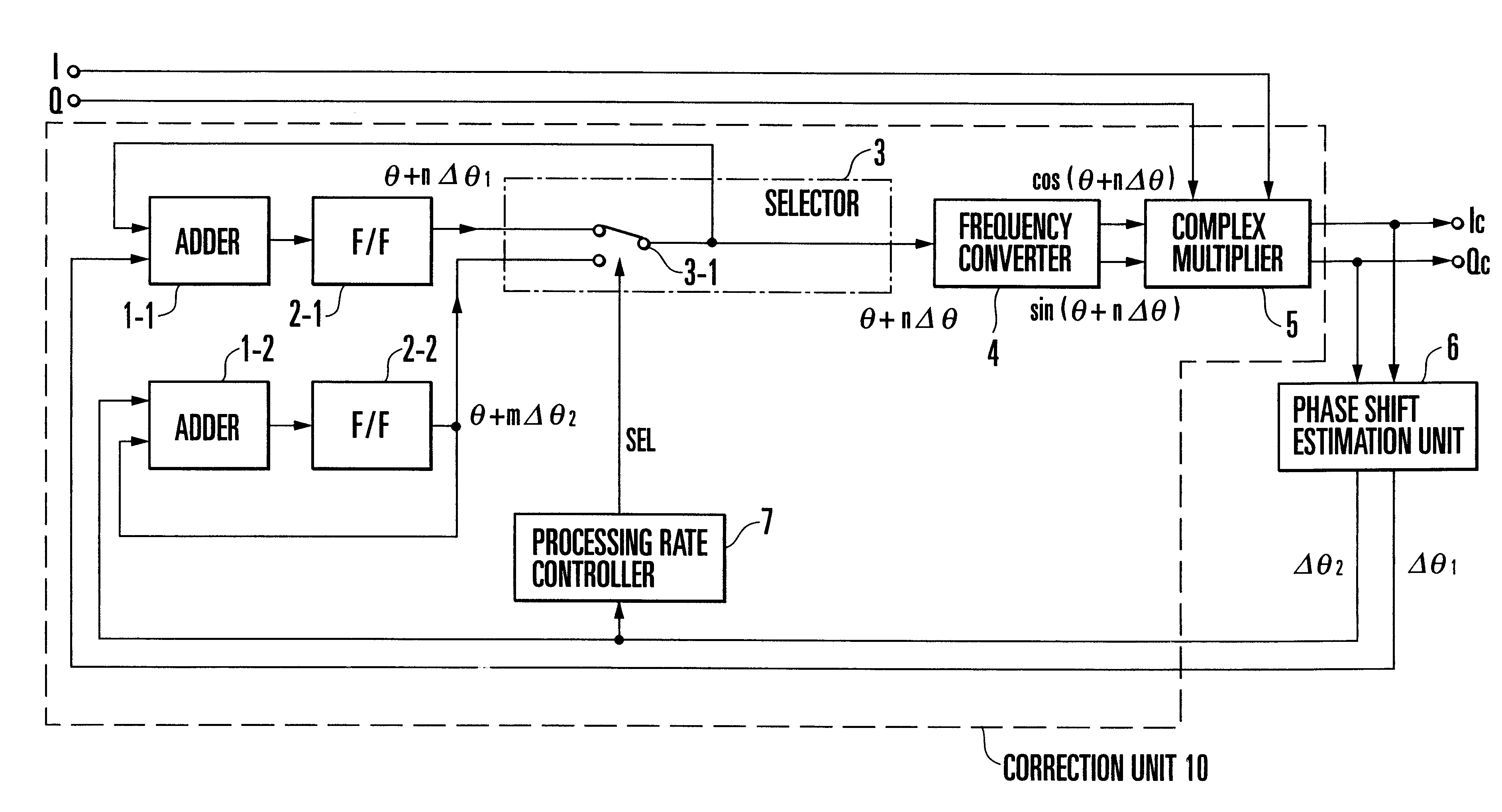
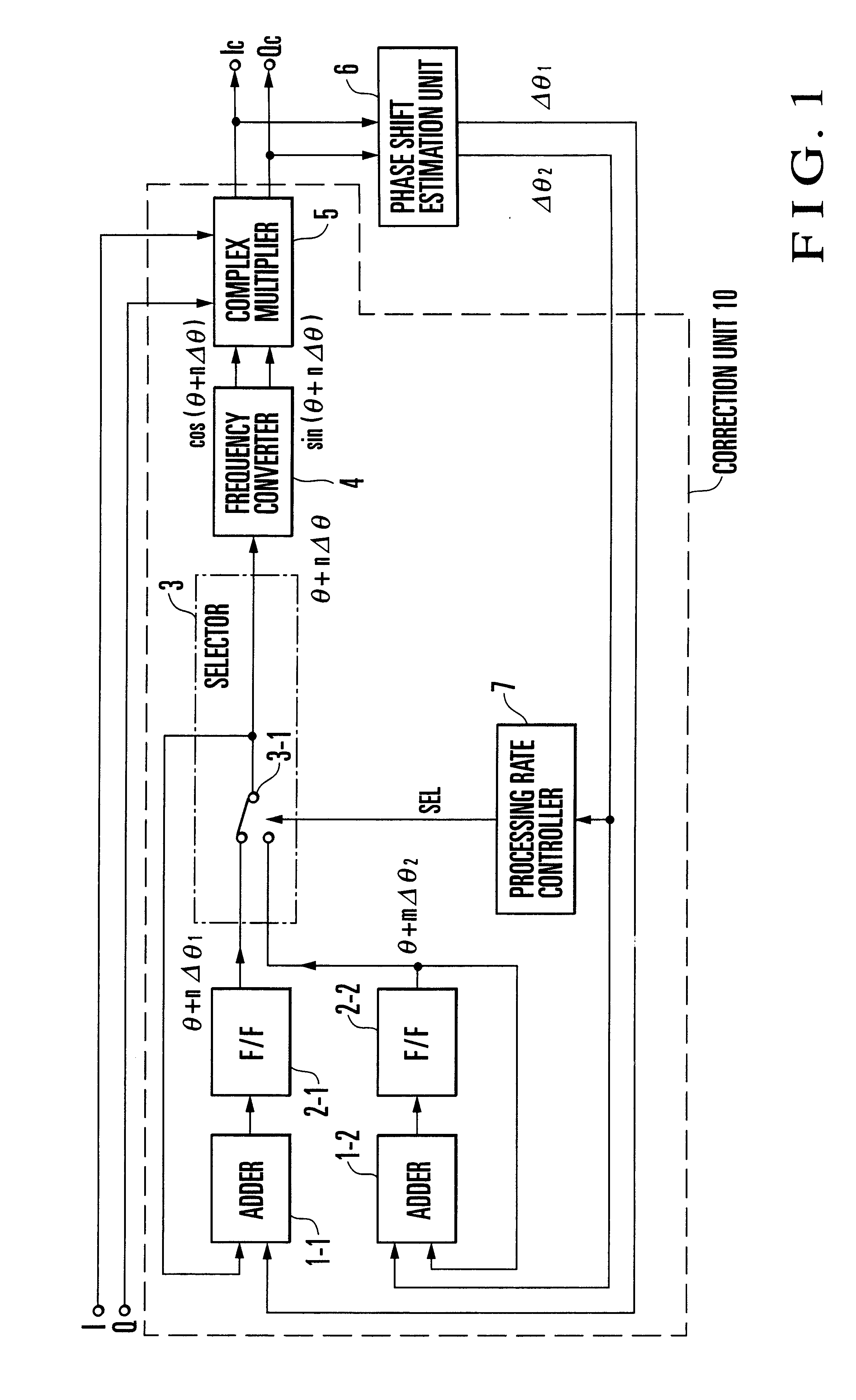
[0023]FIG. 1 shows a frequency offset correction apparatus according to an embodiment of the present invention. As shown in FIG. 1, the frequency offset correction apparatus of this embodiment comprises adders 1-1 and 1-2. The adder 1-1 receives a phase shift (phase change amount) Δθ1 of data of I-Channel (in-phase component), and adds phase shifts in units of bits. The adder 1-2 receives a phase shift (phase change amount) Δθ2 Of pilot signal data of Q-Channel (quadrature component), and adds phase shifts in units of bits.

[0024]The output ports of the adders 1-1 and 1-2 are respectively connected to flip-flops (F / Fs) 2-1 and 2-2. The output port of the flip-flop 2-2 is connected to one input port of the adder 1-2. The output port of the flip-flop 2-1 is connected to a selector 3 for selecting one of the outputs of the flip-flops 2-1 and 2-2. The output port of a switch 3-1 is c...


PUM


Abstract

A frequency offset correction system includes a phase shift estimation unit and correction unit. The phase shift estimation unit estimates a pilot phase shift from pilot signal data for a plurality of bits, and estimates a data phase shift of data from the pilot phase shift for each bit when the frequency offset of a received signal having data of an in-phase component whose bit rate is variable, and pilot signal data of a quadrature component is small. The correction unit sequentially adds data phase shifts and pilot phase shifts estimated by the phase shift estimation unit, and performs frequency offset correction of the received signal using a phase shift obtained by selectively inserting the estimated pilot phase shifts in the added estimated data phase shifts. A frequency offset correction method is also disclosed.

Description

BACKGROUND OF THE INVENTION[0001]The present invention relates to an AFC (Auto Frequency Control) circuit and, more particularly, to a frequency offset correction system and correction method used in the AFC circuit of a CDMA (Code Division Multiple Access) receiver.[0002]As shown in FIG. 5, a conventional CDMA receiver comprises a down converter 11 for receiving an RF (Radio Frequency) signal and converting it into an IF (Intermediate Frequency) signal, a despread unit 12 for spectrum-despreading the IF signal output from the down converter 11, and a demodulator 13 for demodulating an output signal from the despread unit 12 to generate received data.[0003]A CDMA received signal is a signal prepared by modulating a signal into BPSK (Binary Phase Shift Keying) signals by data and pilot signal data of I-Channel (In-phase component) and Q-Channel (Quadrature component), superimposing these signals to modulate them into QPSK (Quadrature Phase Shift Keying) signals, and modulating the re...

Claims


Application Information

Patent Timeline
IPC IPC(8): H04L27/227H04L27/00H04B1/707H03L7/06H04B1/7087
CPCH04L27/2273H04L2027/0087H04L2027/0057H04L2027/003
Inventor MABUCHI, TETSUO
Owner NEC CORP
Why Eureka
Try Eureka