Fuel assemblies in a reactor core and method of designing and arranging same

a fuel assembly and reactor core technology, applied in nuclear elements, nuclear engineering problems, greenhouse gas reduction, etc., can solve the problems of increasing the growth rate of cladding temperature and oxide layer, accelerating corrosion, and reducing the adverse impact of crud deposition. , the effect of cost saving and cost effectiv

a fuel assembly and reactor core technology, applied in nuclear elements, nuclear engineering problems, greenhouse gas reduction, etc., can solve the problems of increasing the growth rate of cladding temperature and oxide layer, accelerating corrosion, and reducing the adverse impact of crud deposition. , the effect of cost saving and cost effectiv

US6891912B1Inactive Publication Date: 2005-05-10ARIZONA PUBLIC SERVICE

Image

  • Fuel assemblies in a reactor core and method of designing and arranging same
  • Fuel assemblies in a reactor core and method of designing and arranging same
  • Fuel assemblies in a reactor core and method of designing and arranging same

Examples


Embodiment Construction

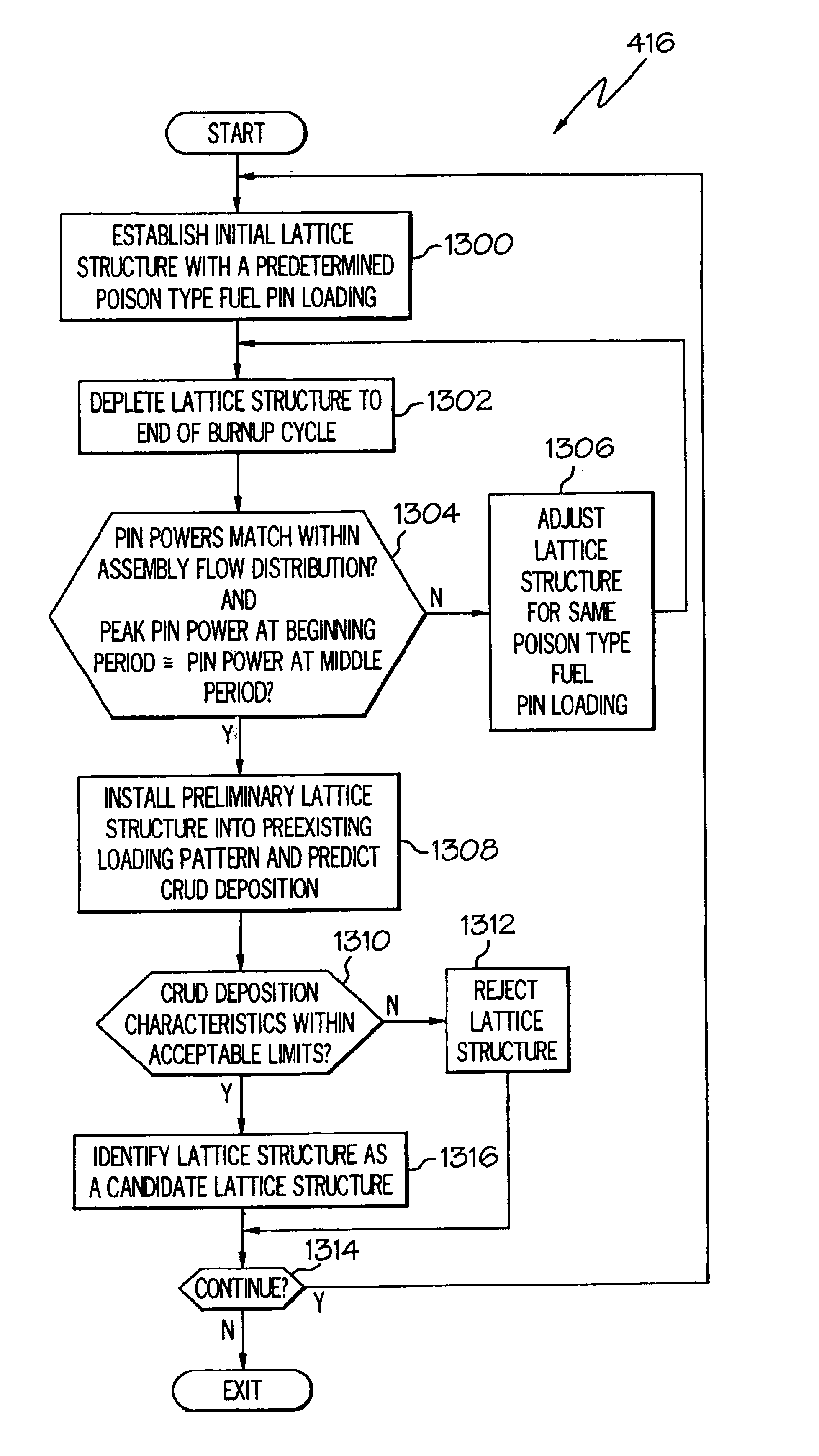
[0033]The present invention predicts the magnitude of crud and oxide deposition on fuel pins within fuel assemblies of a reactor core. The ability to predict crud deposition enables designers to redesign fuel assembly lattice structures and / or generate fuel assembly loading patterns and to so as to minimize the adverse impact of crud deposition. The implementation of the present invention results in the reduction of the overall amount of crud in the reactor core to within manageable levels, while more evenly distributing crud deposition across all fuel assemblies and all fuel pins in the reactor core. The invention is timely and cost effectively implemented by limiting design changes to intra-lattice enrichment splits and burnable poison placement, while disallowing changes in pin diameter, pin pitch, and pin burnable poison type which may require regulator approval.

[0034]Throughout this discussion, items are assigned three-or four-digit reference numbers whose first digit or first ...


PUM


Abstract

A reactor core (104) includes fuel assemblies (202) arranged in a loading pattern (1100) in response to corresponding power levels of the fuel assemblies (202). A crud deposition model (412) is used to predict crud deposition on the fuel assemblies (202) and fuel pins (300) within the fuel assemblies (202). The prediction of crud deposition enables generation of the loading pattern (1100) and design of lattice structures (1600) for the fuel assemblies (202) that results in the reduction of total crud deposition in the reactor core (104) and causes a substantially uniform crud deposition on the fuel assemblies (202) of the reactor core (104).

Description

RELATED INVENTION[0001]The present invention claims priority under 35 U.S.C. §119(e) to: “Taming the Crud Problem—A Utility Perspective,” Provisional U.S. Provisional Patent Application Ser. No. 60 / 392,302, filed 26 Jun. 2002, which is incorporated by reference herein.TECHNICAL FIELD OF THE INVENTION[0002]The present invention relates to the field of nuclear reactors. More specifically, the present invention relates to designing and arranging fuel assemblies in a reactor core to control deleterious crud deposition.BACKGROUND OF THE INVENTION[0003]In a typical nuclear power plant, heat energy is generated by fissioning uranium fuel within a reactor core. The heat energy is then collected in water, also known as coolant, and is carried away from the reactor core either as steam in boiling water reactors or as subcooled water in pressurized-water reactors. In a pressurized-water reactor, the sub-cooled water in the primary cooling loop is used to transfer heat energy to a secondary loo...

Claims


Application Information

Patent Timeline
10 May 2005
Publication
US6891912B1
IPC
G21C19/20
CPC
G21C19/205; G21Y2004/40; G21Y2002/207; Y02E30/30
Inventors
LUKIC, YOVAN D.; SCHMIDT, JEFFREY S.