Multi-aperture beam steering system with wavefront correction based on a tunable optical delay line

a technology of wavefront correction and optical delay line, applied in the direction of optics, optical elements, instruments, etc., can solve the problems of electromechanical systems limited to low response frequencies, parts of electromechanical systems along with size and weight factors are considered to be major limitations of such systems, and the problem is particularly noticeabl

a technology of wavefront correction and optical delay line, applied in the direction of optics, optical elements, instruments, etc., can solve the problems of electromechanical systems limited to low response frequencies, parts of electromechanical systems along with size and weight factors are considered to be major limitations of such systems, and the problem is particularly noticeabl

US6891987B2Inactive Publication Date: 2005-05-10HRL LAB

Image

  • Multi-aperture beam steering system with wavefront correction based on a tunable optical delay line
  • Multi-aperture beam steering system with wavefront correction based on a tunable optical delay line
  • Multi-aperture beam steering system with wavefront correction based on a tunable optical delay line

Examples


Embodiment Construction

[0031]The present invention now will be described more fully hereinafter with reference to the accompanying drawings, in which preferred embodiments of the invention are shown. This invention may be embodied in many different forms and should not be construed as limited to the embodiments set forth herein.

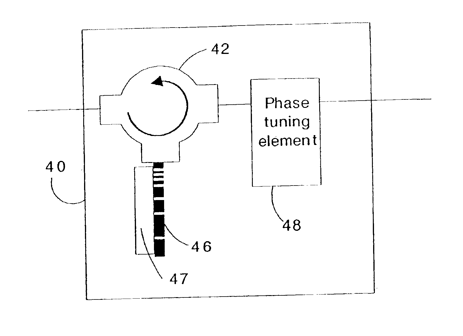
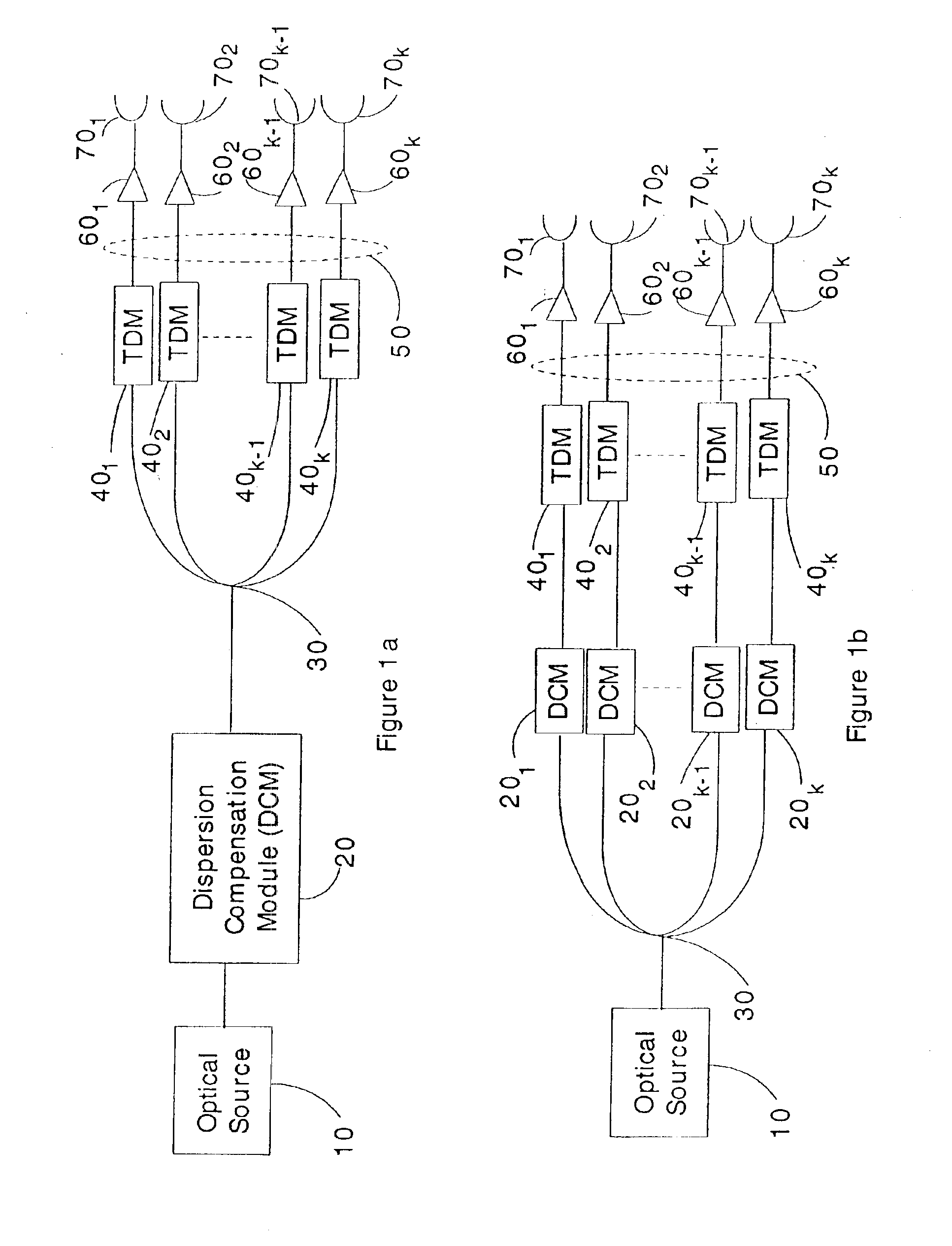
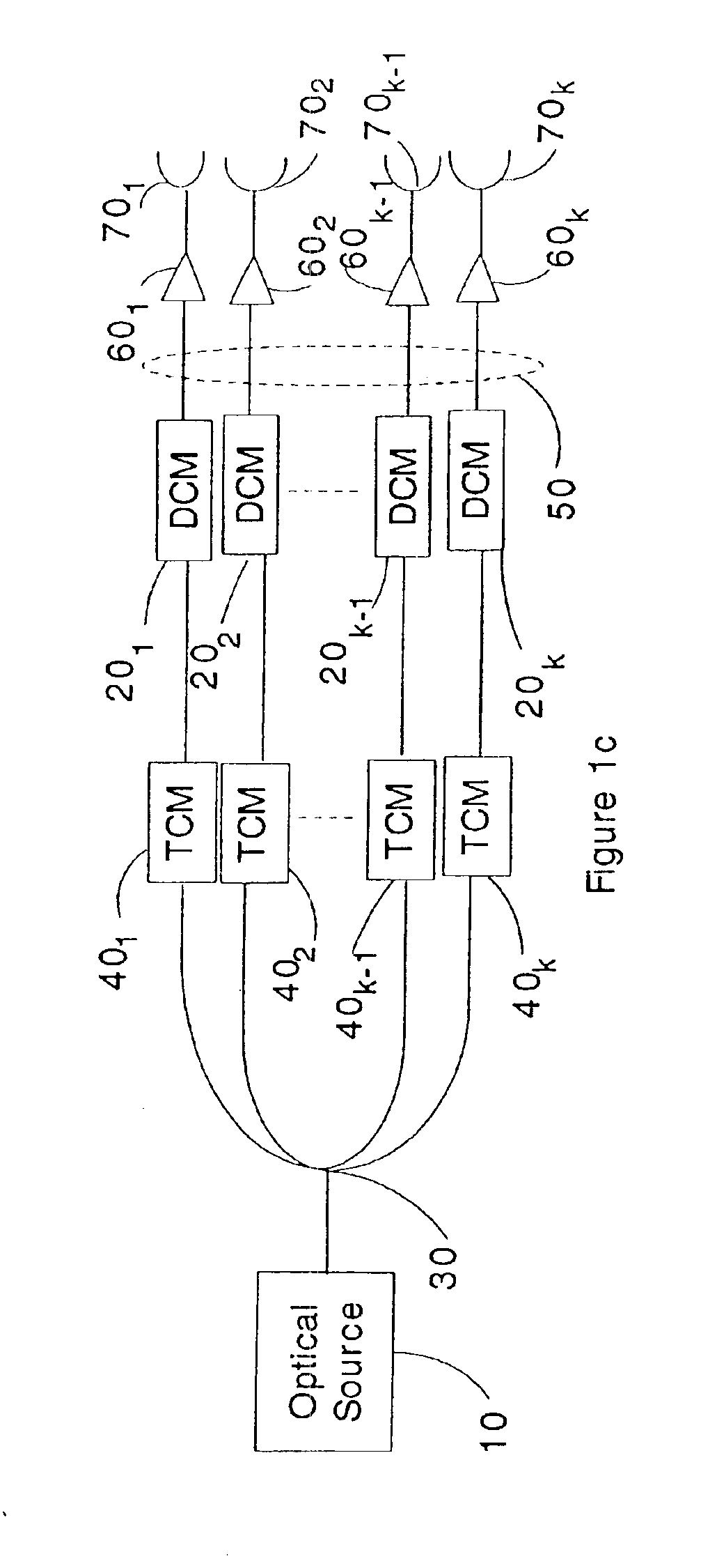
[0032]A block diagram of a preferred embodiment of the present invention is shown in FIG. 1a. An optical source 10 generates a time varying signal that is preferably first passed through an optional dispersion compensation module 20. An example of a time varying signal is a train of optical pulses. The time varying signal is then passed through a 1×N coupler 30, splitting the time varying signal into a plurality of beamlets. Each beamlet is passed through a tunable true-time delay module 40l-40k. The tunable true-time delay modules provide an array of reflected true-time delayed beamlets 50, that may be used in beam-steering applications. Each of the tunable true-time delay modules...


PUM


Abstract

A true-time delay feeder for multiple aperture beam steering devices. The feeder comprises a plurality of tunable time delay modules. The tunable time delay modules provide different delays to different beamlets without changing the spectrum of each beamlet. The tunable true-time delay modules provide for temporal synchronization and spatial coherence of the beam front.

Description

CLAIM OF BENEFIT OF PROVISIONAL APPLICATION[0001]This application claims the benefit of U.S. Provisional application Ser. No. 60 / 375,614, filed on Apr. 24, 2002, which is incorporated herein by reference in its entirety.STATEMENT OF GOVERNMENT INTEREST[0002]This invention was made with Government support under Contract No. DAAB07-01-C-K802 awarded by DARPA. The Government may have certain rights in this invention.FIELD OF THE INVENTION[0003]The present invention relates to optical true-time delay generation. More specifically, the present invention relates to true-time delay generation for multiple aperture optical beam steering devices.BACKGROUND OF THE INVENTION[0004]Optical beam steering is often required where information from an optical beam must be relayed from one location to another. High data rate, secure laser communications, target designation, and laser radar are a few of the applications in which optical beam steering is required. Optical beam steering may be provided b...

Claims


Application Information

Patent Timeline
10 May 2005
Publication
US6891987B2
IPC
G02F1/29; H01Q3/26; H04B10/10
CPC
G02F1/292; H04B10/1121; H01Q3/2682; H01Q3/2676
Inventors
IONOV, STANISLAV I.; SUMIDA, DAVID S.