System and method for joint source-channel encoding, with symbol decoding and error correction

Inactive Publication Date: 2005-05-10
NEBRASKA BOARD OF RGT UNIV OF
View PDF25 Cites 30 Cited by
  • Summary
  • Abstract
  • Description
  • Claims
  • Application Information

AI Technical Summary

Problems solved by technology

The reason is that shared mobile communications channels are restrictive in terms of bandwidth and suffer from such as fading and interference etc., thus making some form of error protection essential, particularly where variable length codes are used.
Further, it is well known that standard approaches to error correction are expensive, in terms of required bandwidth, hence the

Method used


Image

  • System and method for joint source-channel encoding, with symbol decoding and error correction
  • System and method for joint source-channel encoding, with symbol decoding and error correction
  • System and method for joint source-channel encoding, with symbol decoding and error correction

Examples


Embodiment Construction

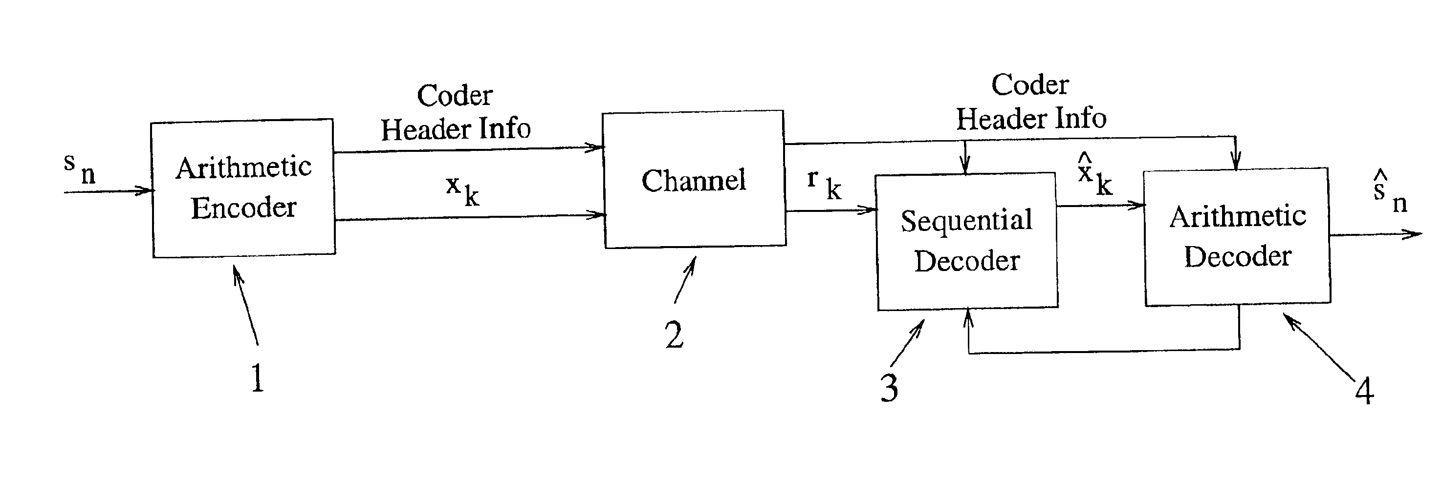
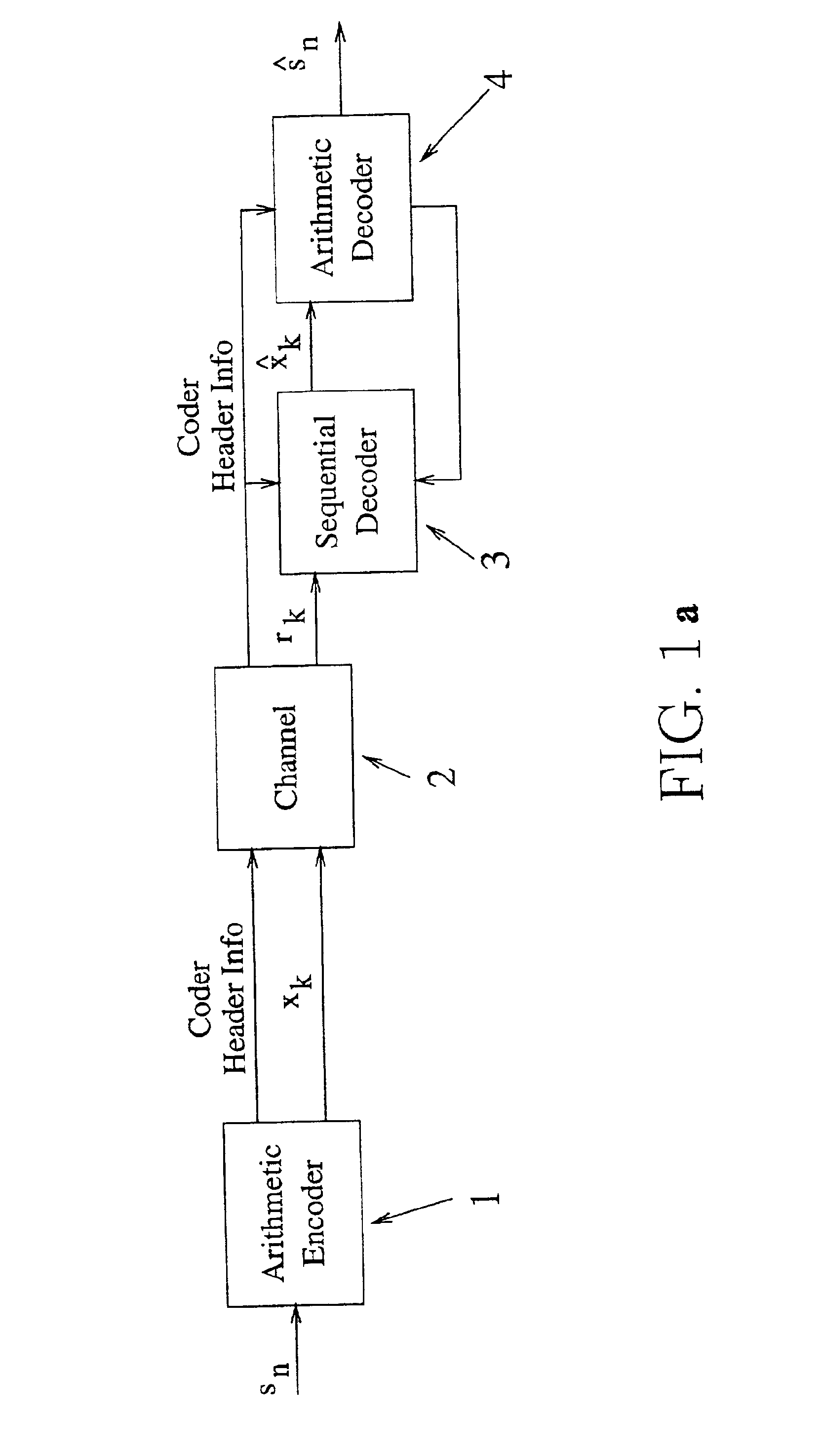
[0126]Turning now to the Drawings, there is shown in FIG. 1a, a preferred embodiment of the present invention system which is applied in a sequential decoding error correction scheme. Shown are a concatenation of an Outer Arithmetic Encoder (1), (which comprises operational Error Detection Space); a Modulation-Transmission means (2), (ie. a Channel) and a functional combination of an Inner Sequential Decoder (3) and an Outer Arithmetic Decoder (4). Note said the Sequential (3) and the Arithmetic (4) Decoders in combination are herein termed a Decoding means. Shown entering to the Arithmetic Encoder (1), (at input means for accepting a sequential plurality of allowed input symbols), are Symbols (sn), which Symbols (sn) are members of an allowed alphabet. Shown exiting the Arithmetic Encoder (1), (at output means for outputting an encoded sequence of bits for allowed symbols input to said encoder means), is a binary bit stream (xk) which arrives at the Sequential Decoder (3) from Modu...


PUM


Abstract

Disclosed is a system and method for joint source-channel encoding, symbol decoding and error correction, preferably utilizing an arithmetic encoder with operational error detection space; and a combination sequential, and arithmetic, encoded symbol decoder structure.

Description

[0001]This Application is a CIP of application Ser. No. 60 / 192,215 filed on Mar. 27, 2000.TECHNICAL AREA[0002]The present invention relates to source symbol encoding, decoding and error correction capability in the context of noisy channels in electronic communication systems. More particularly the prefered present invention is a system and method for joint source-channel encoding and variable length symbol decoding with error correction, comprising arithmetic encoder and combination sequential and arithmetic encoded symbol, decoder means.BACKGROUND[0003]With the increasing popularity of mobile communications there has come renewed interest in joint source-channel coding. The reason is that shared mobile communications channels are restrictive in terms of bandwidth and suffer from such as fading and interference etc., thus making some form of error protection essential, particularly where variable length codes are used. Further, it is well known that standard approaches to error cor...

Claims


Application Information

Patent Timeline
IPC IPC(8): H04L1/00H03M13/07H03M13/00H03M7/40H03M13/47
CPCH03M7/4006H03M13/07H04L1/0056H03M13/6312H04L1/0054H03M13/47
Inventor SAYOOD, KHALIDHOFFMAN, MICHAEL W.PETTIJOHN, BILLY D.
Owner NEBRASKA BOARD OF RGT UNIV OF
Why Eureka
Try Eureka