Piston for spark-ignited direct fuel injection engine

a technology of direct fuel injection and pistons, which is applied in the direction of pistons, combustion engines, machines/engines, etc., can solve the problems of uneven combustion, fuel accumulation on these surfaces is generally more difficult to ignite, and two-stroke engines are more prone to high exhaust emissions

Inactive Publication Date: 2005-05-17
BRP US
View PDF64 Cites 14 Cited by
  • Summary
  • Abstract
  • Description
  • Claims
  • Application Information

AI Technical Summary

Benefits of technology

[0011]A piston for an engine is disclosed having a recess formed in the combustion face. The recess is designed to be located in general alignment with a fuel injector during a portion of the pistons travel within a cylinder when the fuel is injected therein. The recess forms a generally circular shape in a compression face of the piston. The recess extends below the compression face and has a nipple in the center of the recess. The nipple rises smoothly from the base of the recess. A tip of the nipple provides a smooth transition up one side of the nipple and down a second side of the nipple. The recess is off center in the piston and has a w-shaped cross-section with one side of the recess being deeper than a second side of the recess. In this manner, atomized fuel injected into the cylinder is redirected by the recess into a central area of the combustion chamber while maintaining the atomization of the fuel.

Problems solved by technology

Two-stroke engines, by nature, are more prone to high exhaust emissions.
Fuel accumulated on these surfaces is generally more difficult to ignite than atomized fuel mixed with air.
Fuel injected into the combustion chamber that is not thoroughly atomized and dispersed within the combustion chamber can create areas of uneven combustion.
Areas of the combustion mixture having too little fuel lead to a lean burn and areas having too much fuel result in a rich burn.
Additionally, regions of high fuel concentration require more time for the fuel to burn as compared to areas where the fuel concentration is not as high.
Often this time delay allows the temperature in the cylinder to drop to a point where the fuel is not readily burned.
This type of uneven burning, as discussed above, leads to increased hydrocarbon and soot emissions from the engine.
Also, the surface temperatures of the combustion chamber can negatively effect fuel atomization.
This results in a lower temperature burn of the atomized fuel that is in close proximity to these surfaces during the combustion process.
These prior art configurations are not very effective at redirecting fuel to maximize efficiency and minimize emissions in two-stroke engines where the fuel injector is located such that the fuel spray is directed nearly vertically and where it is desired that the fuel be redirected generally back toward the fuel injector.

Method used


Image

  • Piston for spark-ignited direct fuel injection engine
  • Piston for spark-ignited direct fuel injection engine
  • Piston for spark-ignited direct fuel injection engine

Examples


third embodiment

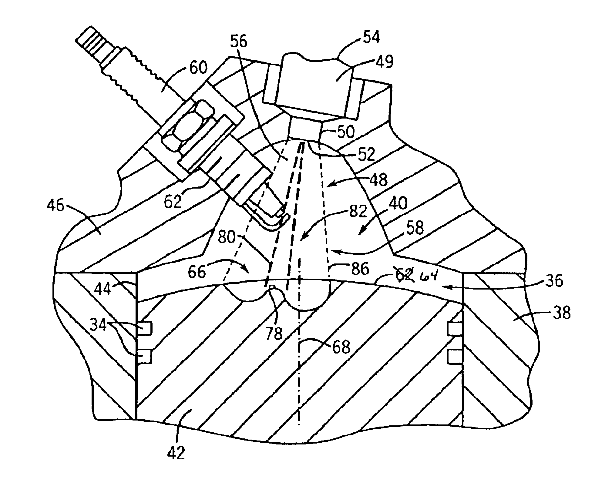
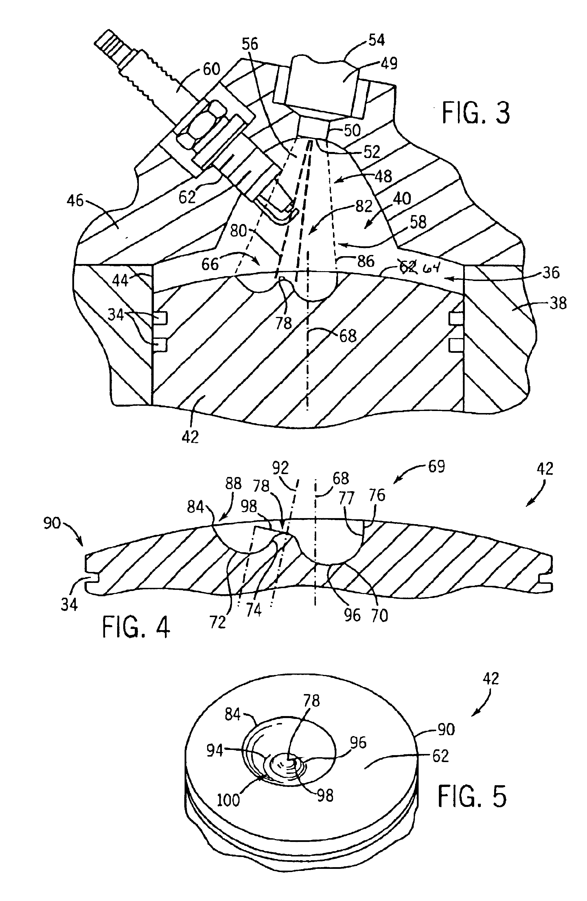
[0041]FIGS. 8 and 9 show the present invention. A recess 140, similar to the recess shown in FIGS. 4 and 5, is located in piston 142. Recess 140 includes a nipple 144 located in a center 146 of recess 140. Nipple 144 is contained below a combustion face 148 of piston 142 and is positioned entirely to one side of a center axis 152 of piston 142. Vertical portion 154 of recess 140 is located proximate center axis 152 of piston 142. The vertical portion 154 of recess 140 leads into a first depression 158. Recess 140 also has a second, shallower, depression 160 which is separated from first depression 158 via nipple 144. Nipple 144, first depression 158, and second depression 160, form a w-shaped cross-section 162 of the recess 140. Nipple 144 has a center axis 164 that, is the center of the w-shaped cross-section 162. Center axis 164 is oriented in piston 14250 that nipple 144 is aligned with a fuel injector. Fuel that is injected into a cylinder containing piston 142 is directed to ni...

first embodiment

[0044]In the present invention, a piston includes a piston skirt with a wrist pin opening therein. The piston includes a piston face that encloses one end of the piston skirt. A bowl-shaped recess with a w-shaped cross-section is formed in the piston face to redirect injected fuel into a central area of a combustion chamber thereby improving combustion.

[0045]In accordance with a further embodiment of the present invention, an internal combustion includes a cylinder with a piston disposed therein. The piston includes a combustion face with a recess formed therein. A nipple, having a center, is located within the recess. A radius extends from the center of the nipple to a low point of the recess. The radius, rotated about the center of the nipple, determines a circumference at which the low point of the recess varies in depth below the combustion face of the piston.

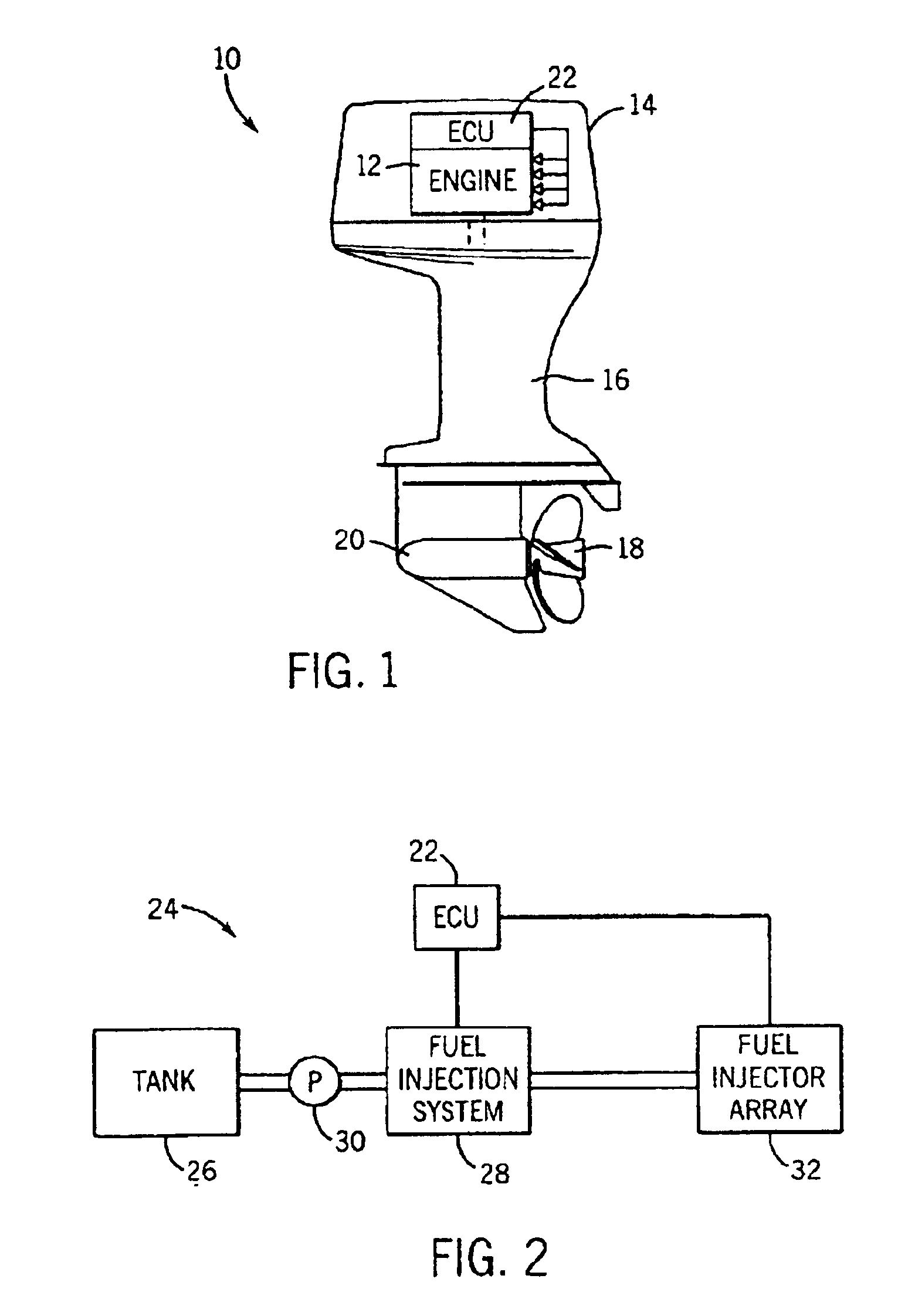
[0046]In accordance with yet another embodiment of the present invention, an outboard motor includes a direct fuel inject...


PUM


Abstract

A piston for an internal combustion engine is disclosed. A bowl-shaped recess is constructed in the combustion face of the piston. The recess has a w-shaped cross-section. The w-shaped cross-section is unsymmetrical and has at least one side that is mostly vertical. The recess is positioned off-center in the face of the piston so that fuel that is injected into the cylinder is redirected by the recess toward a center space of the cylinder thereby improving combustion of fuel in the cylinder and preventing fuel from accumulating about a periphery of the combustion chamber.

Description

BACKGROUND OF INVENTION[0001]The present invention relates generally to pistons for internal combustion engines, and more specifically, to a piston having a uniquely shaped recess formed in the combustion face of the piston.[0002]In general, fuel injected engines include multiple cylinders that receive an atomized fuel injected into the cylinder. The fuel injector provides a fine mist of fuel that mixes with combustion generating gases, generally a mixture of fresh air and any remaining exhaust gases, within the cylinder. This mixture is then compressed and either spark ignited in gasoline engines, or compression ignited in diesel engines. While diesel engines may realize benefits from the present invention, it is primarily directed to fuel injected, spark ignited engines.[0003]In this category of engines, the present invention is applicable to both two-cycle and four-cycle engines. Two-cycle engines are those engines that produce a power stroke with every rotation of the crank shaf...

Claims


Application Information

Patent Timeline
Patent Type & Authority Patents(United States)
IPC IPC(8): F02B23/10F02F3/28
CPCF02B23/101F02F3/28Y02T10/125Y02T10/12
Inventor MONTGOMERY, DAVID T.STRAUSS, SEBASTIAN
Owner BRP US
Why Eureka
Try Eureka