
Structure for converting a mechanical joint to a fusion joint

a technology of fusion joint and mechanical joint, which is applied in the direction of turning machines, turning machines, gang saw mills, etc., can solve the problems of requiring scrapping of the entire installation and no effective way of fixing the coupling

Inactive Publication Date: 2005-05-17
ELSTER PERFECTION CORP
View PDF9 Cites 3 Cited by
  • Summary
  • Abstract
  • Description
  • Claims
  • Application Information

AI Technical Summary

Benefits of technology

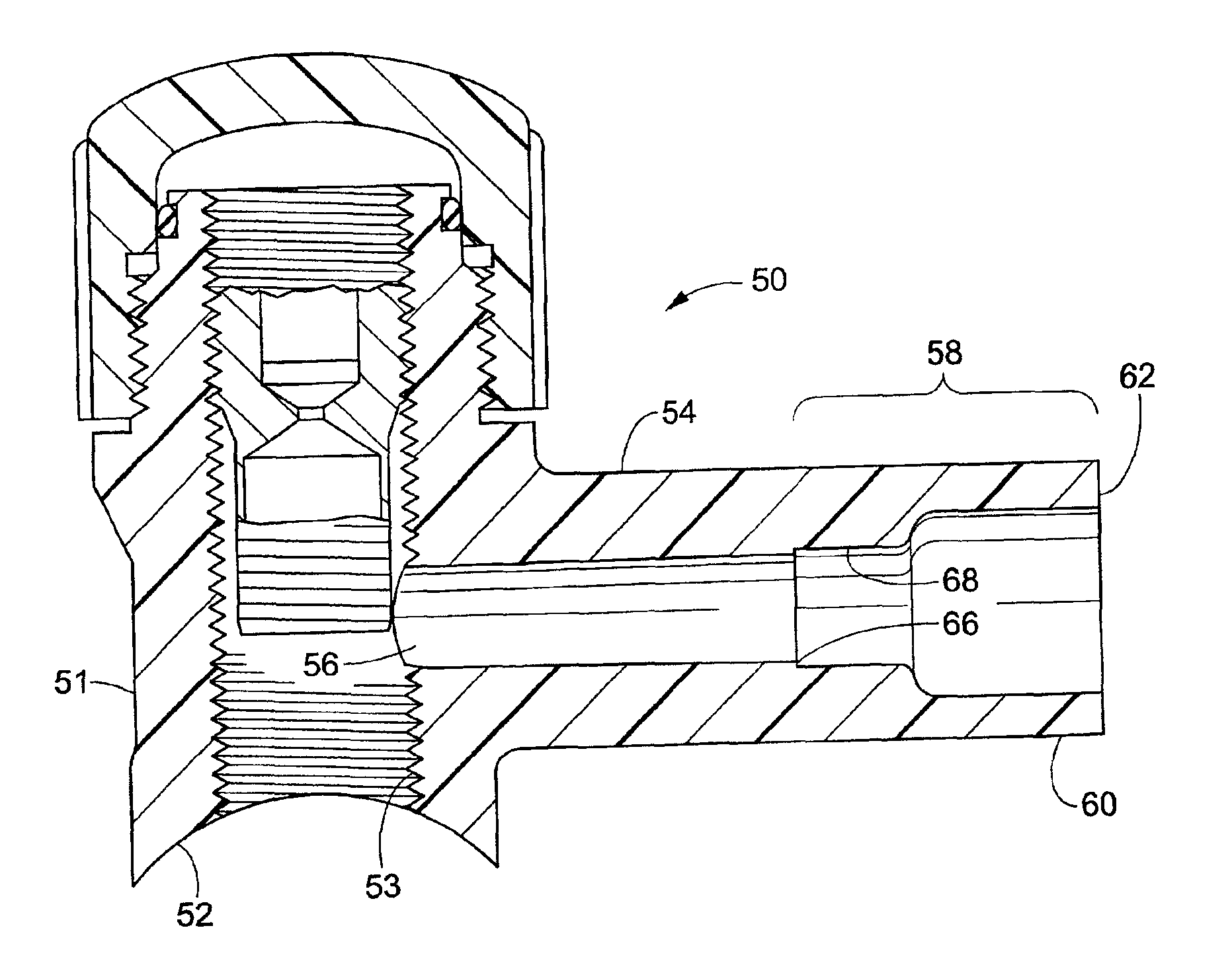
[0014]In accordance with a second aspect of the invention, the converter is adapted to receive a facing tool inserted in the converter passage during a facing operation for removing portions of the severed end to form a faced end such that the fusion surface extends from the faced end for a uniform distance d1 and d1≧FM, and the stop is adapted to abut the facing tool thereby preventing the further insertion of the facing tool and the further removal of portions of the severed end.

Problems solved by technology

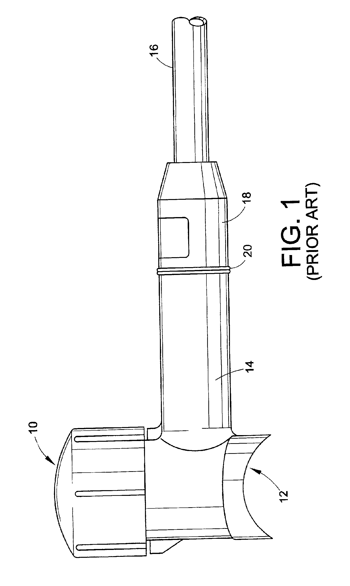
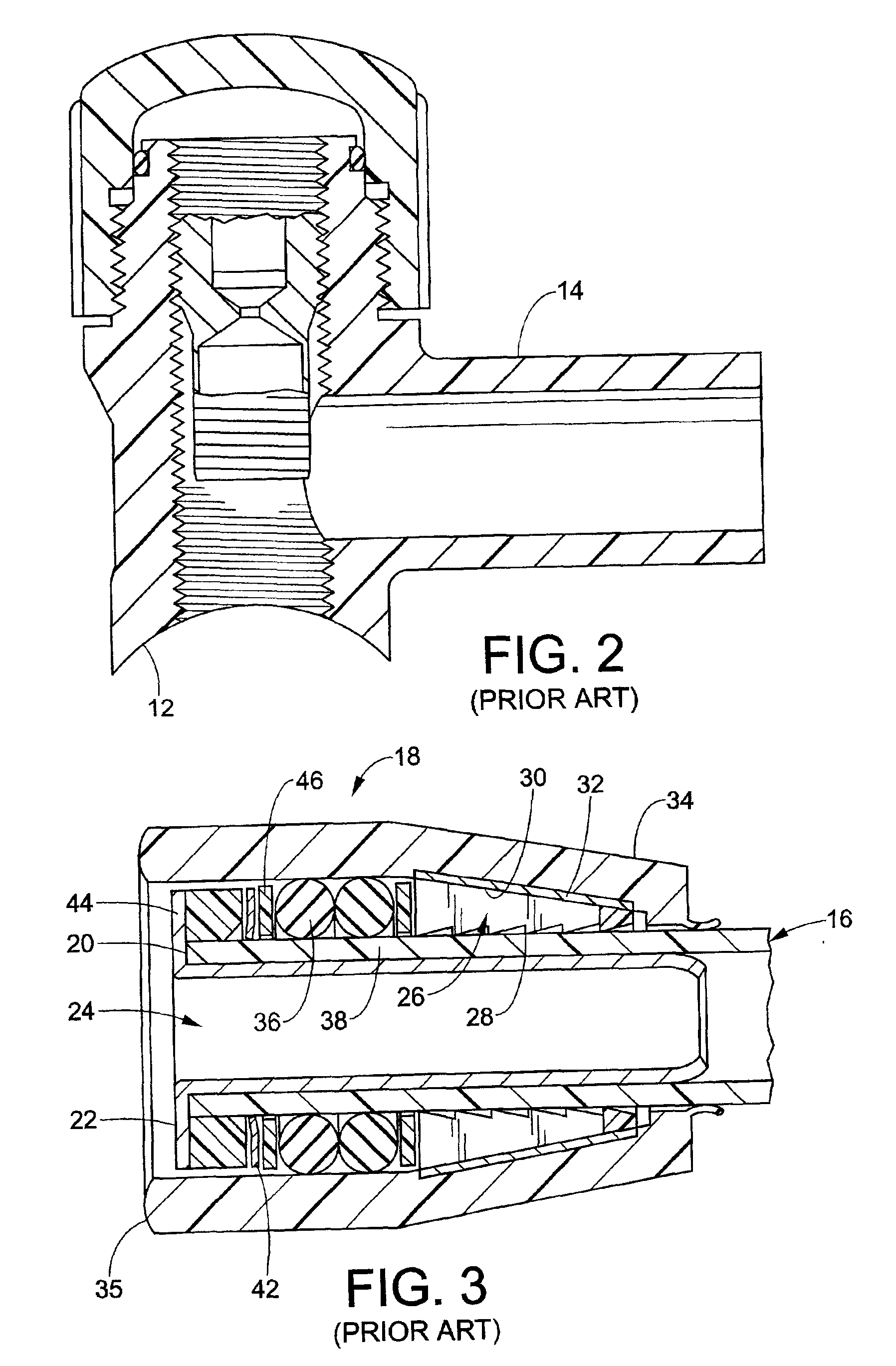
In the event that a leak should be found in the mechanical coupling 18, there is no effective way to repair the coupling since the internal components are not accessible.
Since there is no effective way to gain access to the sealing components of the mechanical coupling 18 and since it is not possible to withdraw the pipe 16 once inserted, a leak will normally require scrapping of the entire installation.

Method used


Image

  • Structure for converting a mechanical joint to a fusion joint
  • Structure for converting a mechanical joint to a fusion joint
  • Structure for converting a mechanical joint to a fusion joint

Examples


Embodiment Construction

[0036]This invention is directed to structure and method for dealing with a leak as may be found in a mechanical coupling 18 which grips and seals a pipe, such as the type shown in FIG. 3.

[0037]Referring to FIGS. 4-6, a fusion tapping tee according to the invention is shown generally at 50. The fusion tapping tee 50 can be formed of plastic, such as polyethylene, though alternatively, it may be formed of any material suitable for forming a fusion joint. The tapping tee 50 includes a tower body 51 having an arcuate portion 52 with a radius approximating the outside radius of a gas main. A tower passage 53 extends through the tower body 51 for communicating with the gas main M when tapped in any known manner.

[0038]The tapping tee 50 further includes a branch 54 extending from the tower body 51. The branch 54 includes an inner surface 56 forming branch passage communicating with the tower passage 53. The tapping tee 50 also includes a converter 58 having an inner surface 59 forming a c...


PUM

PropertyMeasurementUnit
Lengthaaaaaaaaaa
Thicknessaaaaaaaaaa
Diameteraaaaaaaaaa

Abstract

The converter for converting a mechanical joint to a socket fusion joint includes a body having an inner surface, a stop disposed on the inner surface, and a fusion surface extending from the stop for a distance d1. The converter also includes a marker disposed on the outer surface for providing a reference location as to where the body can be severed to keep d1≧FM, wherein FM is the minimum fusion surface length allowable for the fusion socket joint. A method for repairing a leaking mechanical joint is provided which includes severing the mechanical coupling from the converter and the pipe. The method also includes performing a facing operation on the converter end surface to form a faced end such that the fusion surface extends between the faced end and a stop for an axial distance d1≧FM. The method also includes delineating a stab depth measurement on the outer surface of the pipe, inserting the pipe into the passage until the stab depth measurement is adjacent the faced end, and forming a socket fusion joint having a uniform fusion length FL=d1.

Description

CROSS REFERENCE TO RELATED APPLICATIONS[0001]This application claims the benefit under 35 U.S.C. 119(e) of the provisional application Ser. No. 60 / 296,346 filed Jun. 6, 2001, which is hereby incorporated by reference herein.BACKGROUND OF THE INVENTION[0002]The present invention relates generally to the art of joining conduits such as plastic pipes together and, more particularly, to the art of converting a mechanical joint to a fusion joint. The invention will be described in connection with a tapping tee for a plastic natural gas main, but those of ordinary skill in the art will quickly recognize that the invention has broader application to other systems including but not limited to plastic pipe unions, elbows, tees, and in-line connectors.[0003]Tapping tees are generally known in the art and used to provide structure for tapping into a gas main so that gas can be conducted from the main to a home or business. One example of a tapping tee, known as a saddle fusion tapping tee, is ...

Claims


Application Information

Patent Timeline
IPC IPC(8): B23B5/16B23B5/00F16L47/02F16L47/03
CPCB23B5/168F16L47/03B23B2226/61Y10T29/49817Y10T29/49403Y10T29/49821Y10T29/53Y10T29/53552Y10T83/04Y10T83/0596Y10T83/68Y10T83/7587Y10T137/0318Y10T137/0447Y10T137/6123
Inventor ROBISON, DAVEPASSERELL, STEVEN J.KNAUS, JASON
Owner ELSTER PERFECTION CORP
Learn More