Apparatus for loading and unloading aircrafts

a technology for aircrafts and aircraft, applied in the field of aircrafts for loading and unloading, can solve the problems of relatively high physical damage risk and short time available, and achieve the effects of convenient replacement, convenient adjustment, and efficient control of both conveyor parts

Inactive Publication Date: 2005-05-17
MV INVEST APS
View PDF34 Cites 19 Cited by
  • Summary
  • Abstract
  • Description
  • Claims
  • Application Information

AI Technical Summary

Benefits of technology

[0025]It is according to the invention particularly advantageous when the front end of the second conveyor part is provided with a control means connected to all the driving means of the apparatus in such a manner that an operator present inside the aircraft can guide said means by activating said control means. As a result the operator has an efficient control of both conveyor parts.
[0026]The conveyor units may according to the invention be interconnected by means of releasable coupling means with the result that the conveyor units are easily replaced and it is possible, if desired, to adjust the number thereof to the prevailing requirements.
[0027]Furthermore, the bridge member may according to the invention comprise guiding means for guiding the second conveyor part while it is moved inwards and outwards of the cargo compartment of the aircraft. The resulting movement can be performed in a relatively easy manner.
[0028]Moreover, at least some of the coupling means of the conveyor units may according to the invention be such that adjacent conveyor units can be mutually displaced transverse to the conveying direction with the result that they are very easily adjusted to the dimensions of the cargo compartment.

Problems solved by technology

The latter is due to the facts that the time available is often very short and that the cargo compartment is of such a small size that the person in question must lie on his knees or sit down inside said cargo compartment while handling the luggage.
Accordingly, a relatively high risk of physical damages applies.
In addition, the auxiliary equipment must be movable into and out of the aircraft in a relatively quick manner due to the rather short period available.

Method used


Image

  • Apparatus for loading and unloading aircrafts
  • Apparatus for loading and unloading aircrafts
  • Apparatus for loading and unloading aircrafts

Examples


second embodiment

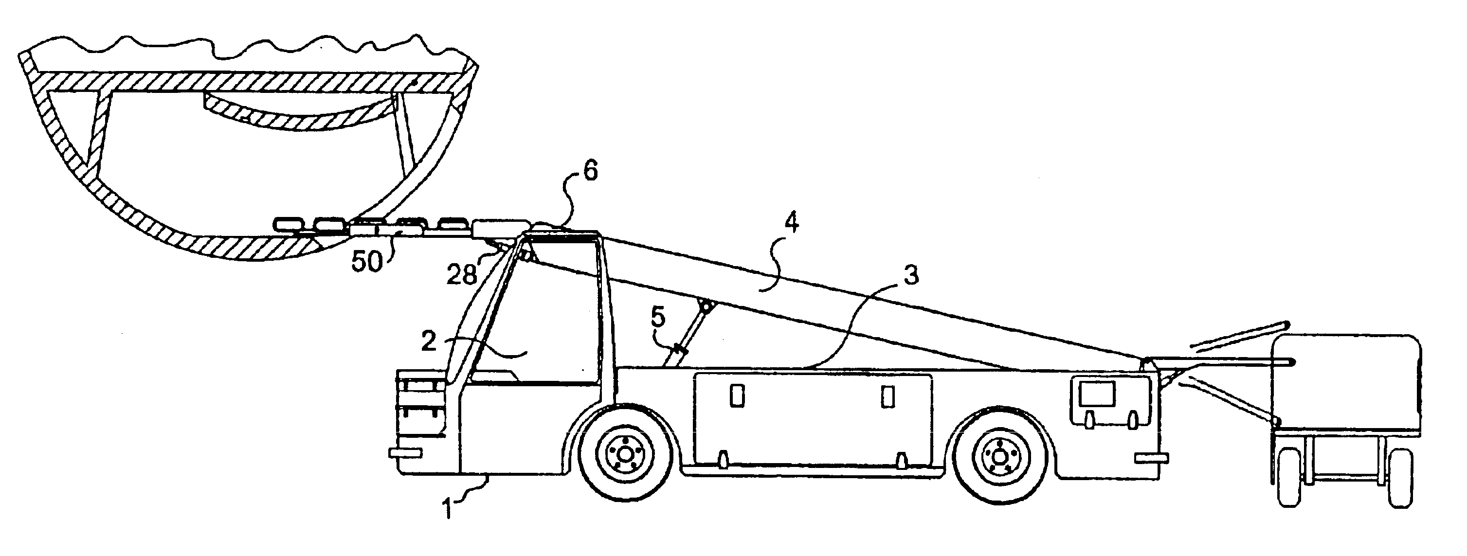
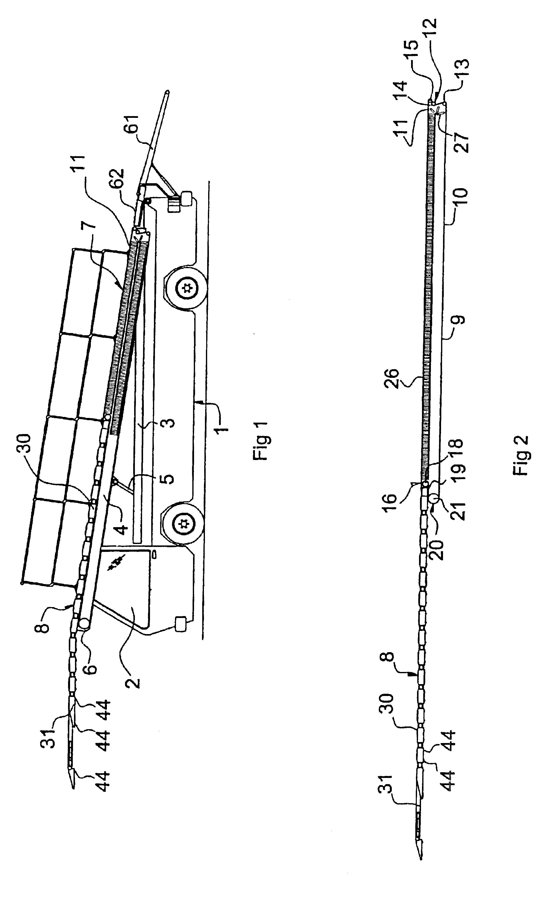
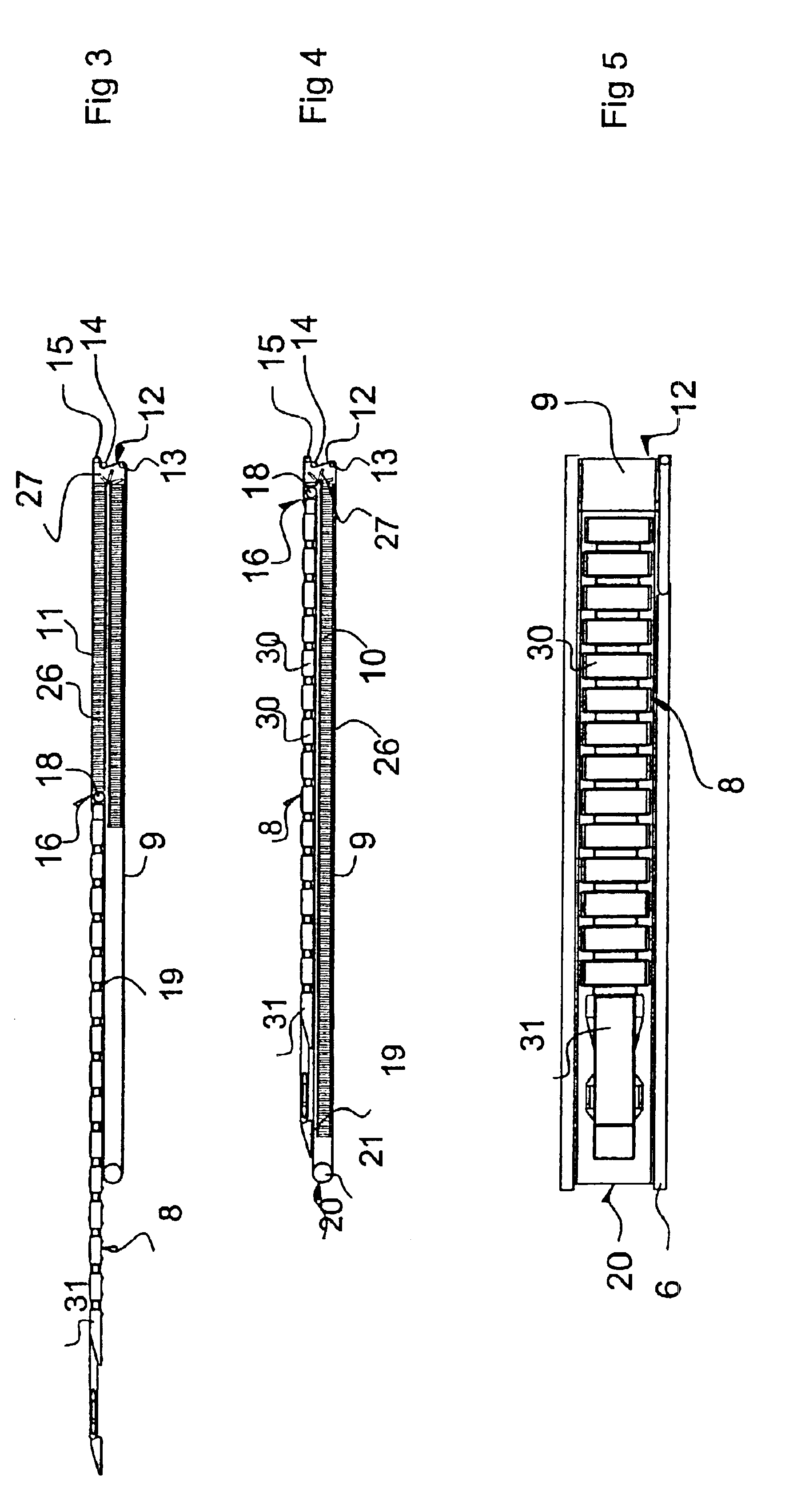
[0064]FIGS. 18 and 19 illustrate the apparatus according to the invention. Here the conveyor paths of both the first and the second conveyor part 7 and 8 are formed by a coherent row of conveyor units 30 and 31. The rear end of this row of conveyor units is received in a compartment 65 below the platform 3 of the vehicle 1, and from this position it is moved through the rear end of the vehicle upwards onto the ramp as the front end of the row is moved into the cargo compartment 52 of the aircraft 53. This embodiment is particularly suited for use in connection with particularly long cargo compartments 52 requiring a relatively high number of conveyor units.

[0065]The individual members, and especially the conveyor units of the second conveyor part 8 are made mainly of plastic materials in response to the desired strength. Furthermore, additional conveyors 61 and 62 can be mounted at the rear end of the apparatus so as to facilitate the transition between the equipment for the advanci...

third embodiment

[0070]FIG. 24 illustrates the invention. Here the conveyor path of the first conveyor part 7 is formed by a first endless conveyor belt 110 mounted above the path of the conveyor units 70 between a compartment 111 and the bridge member 105. The first conveyor part 7 comprises furthermore a front conveying means with a second continuous belt 112, and which in front tapers in such a manner that the cargo items being handled pass in a relatively easy manner to and from the first endless conveyor belt of the first conveyor part 7. As indicated in FIG. 24, rails 113 are provided in the compartment 111, and the conveyor units 70 can run on said rails by means of the wheels 76 while the endless conveyor belts face downwards.

[0071]The moving of the conveyor units 70 to and from the compartment is carried out by means of a driving, endless conveyor belt 114 which co-operates with the bottom side of the conveyor units 70 in a suitable manner, such as by way of friction.

[0072]The invention has...


PUM


Abstract

An apparatus for loading and unloading aircrafts comprises a tiltable first conveyor part (7) adjustable in height and provided with a conveyor path (11) advancing and removing luggage (59), such as suitcases, parcels and the like cargo items, to and from the apparatus. The apparatus comprises further a second conveyor part (8) extendable from the first conveyor part and being adapted to be moved through an opening in the aircraft and into the cargo compartment of said aircraft. This second conveyor part (8) comprises a conveyor path advancing or removing the luggage to or from the storing site inside the cargo compartment. The second conveyor part (8) comprises a plurality of pivotally interconnected conveyor units (30, 31) with their respective activatable conveyor paths and their respective sets of wheels (44).

Description

[0001]This application is a continuation of application Ser. No. 10 / 169,361, filed Oct. 23, 2002 which is a 371 of PCT / DK01 / 00012, filed Jan. 10, 2001.TECHNICAL FIELD[0002]The invention relates to an apparatus for loading and unloading aircrafts, where said apparatus comprises a tiltable first conveyor part adjustable in height and comprising a conveyor path advancing and removing luggage, such as suitcases, parcels and the like cargo items, to and from a second conveyor part connected to and being extend able from said first conveyor part, where said second conveyor part is adapted to be extended into the aircraft through an opening therein and into the cargo compartment of said aircraft, and where said second conveyor part comprises a conveyor path advancing and removing the luggage to or from the storing site inside the cargo compartment.[0003]In connection with the loading and unloading of small aircrafts, such as DC 9, MD 80'ies and Boeing 737 etc., viz. the so-called narrow bo...

Claims


Application Information

Patent Timeline
Patent Type & Authority Patents(United States)
IPC IPC(8): B64F1/32B64F1/00B60P1/36B65G21/14B65G41/00
CPCB65G67/08B64F1/32B64F1/324
Inventor TH.O SLASHED.GERSEN, LARS
Owner MV INVEST APS
Why Eureka
Try Eureka