Substrate delivering robot

a robot and substrate technology, applied in the field of substrate delivery robots, can solve the problems of increasing the installation area of the robot, and achieve the effect of reducing the minimum turning radius and minimizing the installation area

Inactive Publication Date: 2005-05-17
YASKAWA DENKI KK
View PDF12 Cites 64 Cited by
  • Summary
  • Abstract
  • Description
  • Claims
  • Application Information

AI Technical Summary

Benefits of technology

[0004]The invention has been made to solve such a problem and has an object to provide a substrate delivering robot capable of decreasing the minimum turning radius in the contraction state of the robot and minimizing an installation area even if a plurality of forks are provided.
[0006]As described above, according to the invention, it is possible to obtain such a great advantage as to provide a substrate delivering robot capable of decreasing a minimum turning radius in the contraction state of the arm and minimizing an installation area even if a plurality of forks are provided.

Problems solved by technology

For this reason, there is a problem in that the minimum turning radius of the substrate delivering robot is large also in the contraction state of an arm, resulting in an increase in the installation area of the robot.

Method used


Image

  • Substrate delivering robot
  • Substrate delivering robot
  • Substrate delivering robot

Examples


Embodiment Construction

[0014]An embodiment of the invention will be described below with reference to the drawings.

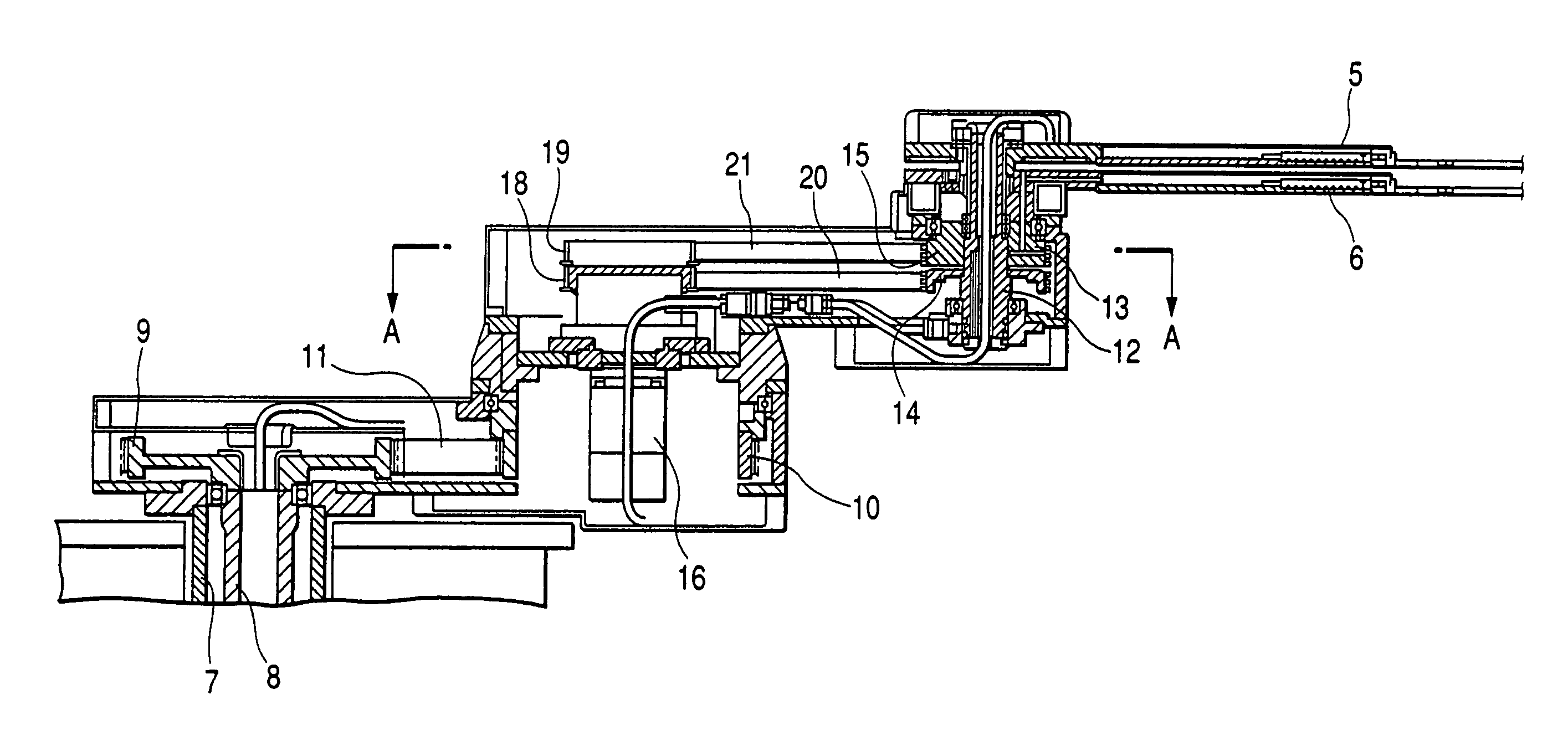
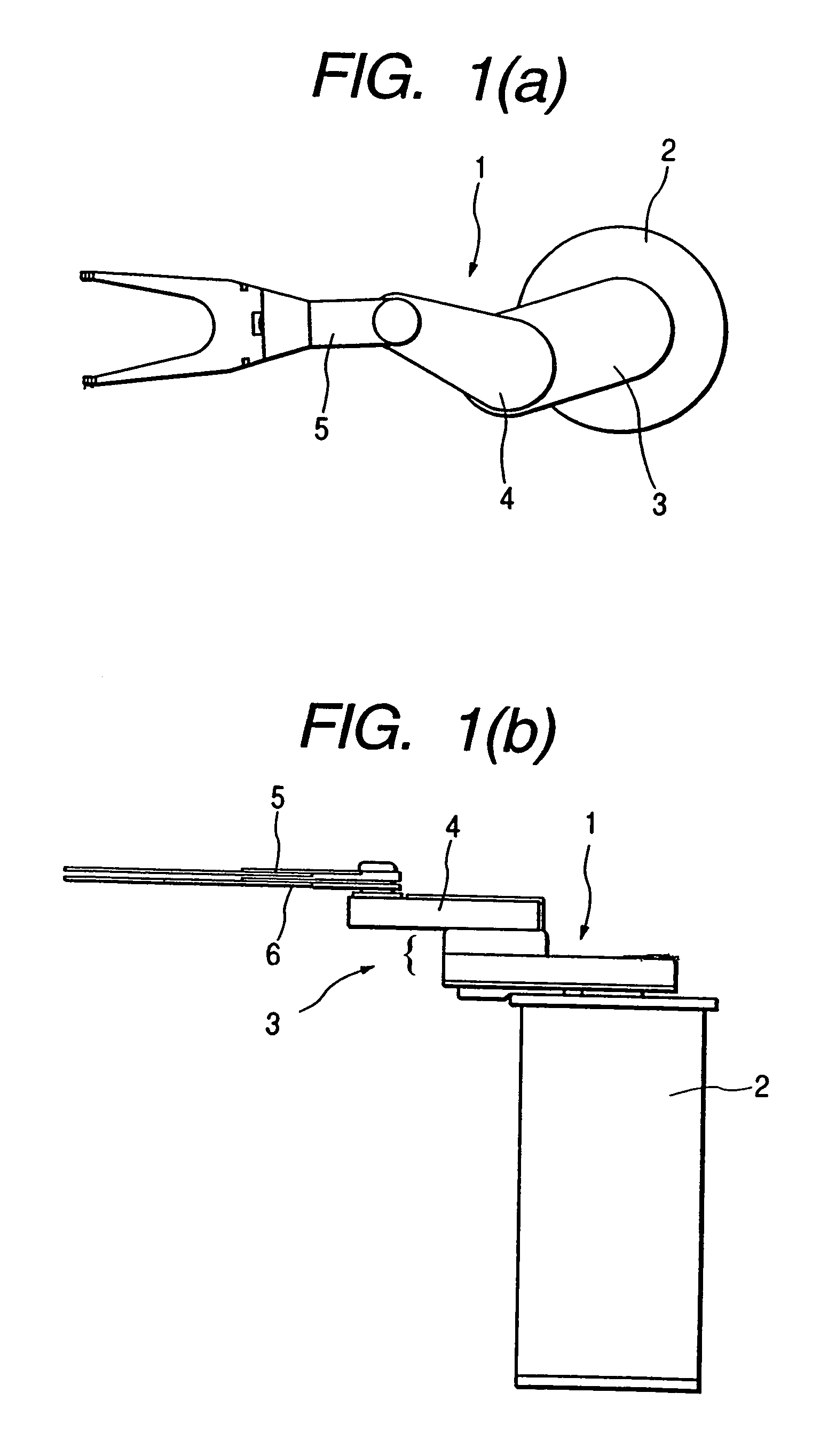
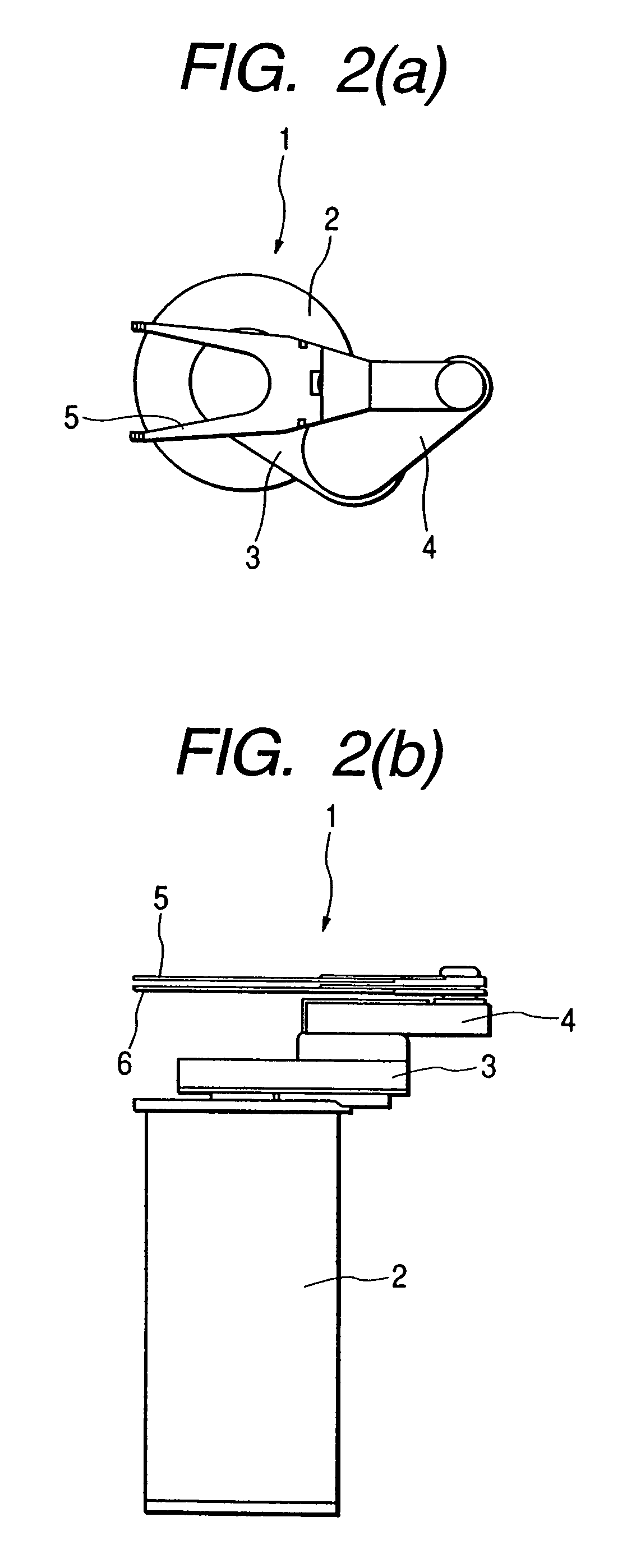
[0015]FIG. 1 shows a state in which an arm is extended in a substrate delivering robot according to the embodiment of the invention, FIG. 1(a) being a plan view and FIG. 1(b) being a side view. FIG. 2 shows a state in which the arm is contracted in the substrate delivering robot according to the embodiment of the invention, FIG. 2(a) being a plan view and FIG. 2(b) being a side view. FIG. 3 is a side sectional view showing the structure of an arm section, FIG. 4 is a sectional view taken along an A—A line in FIG. 3, FIG. 5 is a view showing two motors in FIG. 3 seen in a direction of B, and FIGS. 6(a) and 6(b) show the plan views showing the operation of the substrate delivering robot according to the invention, FIG. 6(a) showing a state in which a processed substrate is taken out and FIG. 6(b) showing a state in which an unprocessed substrate is mounted.

[0016]As shown in FIGS. 1(a) and 1(b) ...


PUM


Abstract

A robot for carrying a substrate in which minimum turning radius is small when the arm is retracted although a plurality of forks are provided and installation area can be minimized. The robot comprises a fixed base, a first turnable arm linked with the fixed base, a second turnable arm linked with the first arm, and a turnable fork linked with the second arm, wherein the fork comprises a plurality of first and second independent forks. The first and second forks are fixed coaxially and vertically in two stages to the forward end part of the second arm such that they can turn independently and first and second fork drive motors are disposed in the second arm.

Description

TECHNICAL FIELD[0001]The present invention relates to a substrate delivering robot to be used in a semiconductor manufacturing apparatus.BACKGROUND ART[0002]As shown in FIG. 7(a), a conventional general substrate delivering robot 1A for delivering a thin plate-shaped substrate such as a semiconductor wafer or a liquid crystal glass substrate is constituted by a fixed base 2A, a first arm 3A coupled turnably to the fixed base 2A, a second arm 4A coupled turnably to the first arm 3A, and a fork 5A for substrate mounting which is turnably coupled to the second arm 4A. In the case in which such a substrate delivering robot can be caused to mount two substrates at the same time, the fork 5A having a central part turnably supported, one of ends provided with a processed substrate mounting section 5Aa for mounting a processed substrate and the other end provided with an unprocessed substrate mounting section 5Ab for mounting an unprocessed substrate is coupled turnably to the tip portion o...

Claims


Application Information

Patent Timeline
Patent Type & Authority Patents(United States)
IPC IPC(8): B65G49/06B65G49/05H01L21/677H01L21/67B25J9/06B25J15/08B65G49/07
CPCB65G49/067H01L21/67742H01L21/67766H01L21/67745Y10T74/20317
Inventor SUZUKI, TAKEOOGASAWARA, MASARUOMATA, TOSHIO
Owner YASKAWA DENKI KK
Why Eureka
Try Eureka