

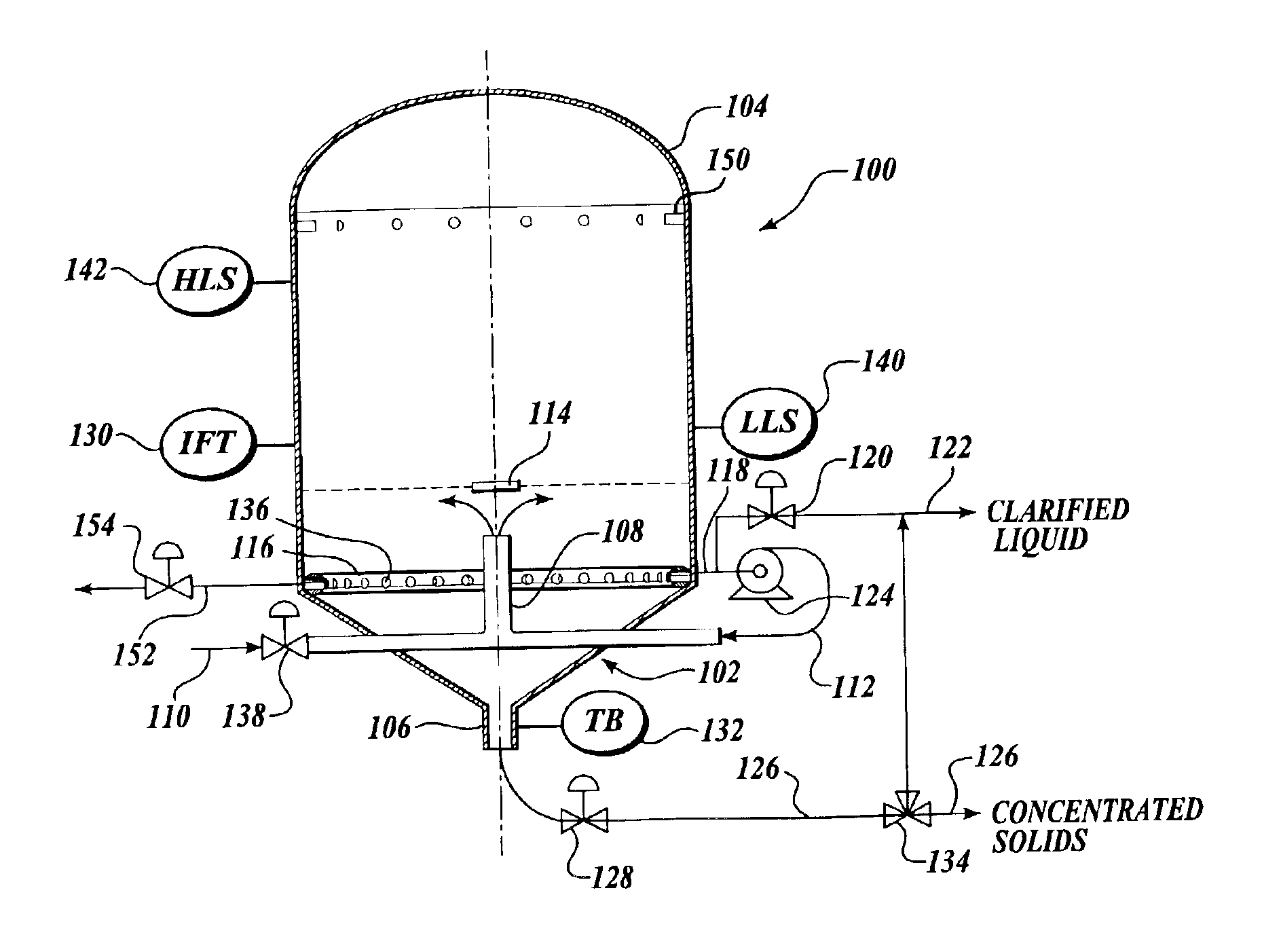
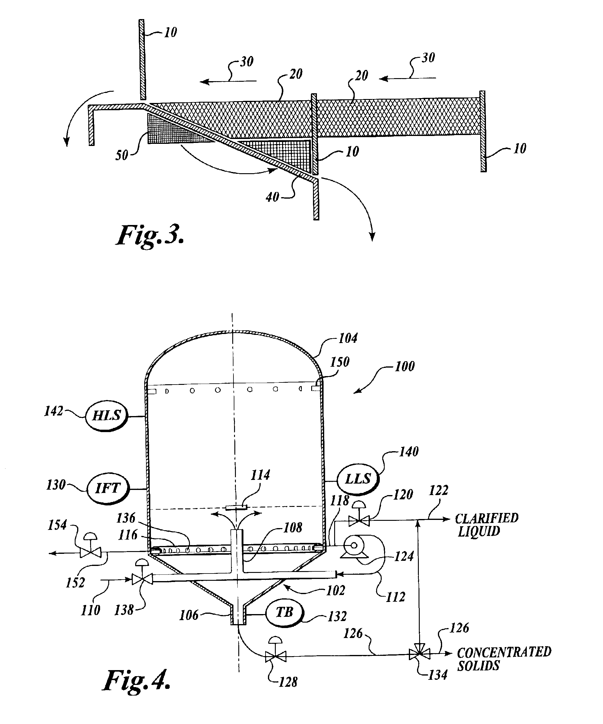
Solids accumulating flotation separator
a flotation separator and solids technology, applied in the direction of separation process, filtration separation, evaporation, etc., can solve the problems that the previous flotation separation system failed to recognize the importance of continuous, and achieve the effect of reducing the cost of separation, reducing complexity, and being easy to automa
- Summary
- Abstract
- Description
- Claims
- Application Information
AI Technical Summary
Benefits of technology
Problems solved by technology
Method used
Image

Examples
example 1
[0080]A solids accumulating separator according to the present invention was operated on two occasions at the Don Aardema Dairy in Wendell, Id. At the Aardema Dairy, flush manure is first processed through a FAN separator to remove coarse solids. The liquid is then processed through a gravity separator. Liquid from the gravity separator was processed in the solids accumulating separator of the present invention.
[0081]Both the influent liquid (Column (2)) to the solids accumulating separator and the clarified liquid effluent (Column (3)) from the separator were analyzed. The thickened solids (Column (5)) were also analyzed. Table 1 shows the results, wherein Column (4) is the percent removed for various constituents of the influent feed stream.
[0082]
TABLE 1ColumnColumn(2)(5)InfluentColumn (3)SolidsConcen-Liquid EffluentColumnConcen-ColumntrationConcentration(4)tration(6)Column(mg / L)(mg / L)Removal(mg / L)Increase(1)pH = 6.85pH = 7.13(%)pH = 6.38(%)Suspended7,4403,03059.27—SolidsCOD15,100...
example 7
[0098]Referring now to Table 8, a comparison of the float blanket depth and the cycles per day required for the particular float blanket depth is shown. Column (3) shows the percent loss of theoretical capacity as compared to an infinitely high float blanket depth. The deeper the float blanket, the less the required number of cycles and the greater the capacity of the solids accumulating flotation separator to remove solids. Accordingly, solids accumulating flotation separators are operated in a manner that seeks to have the greatest possible float blanket depth for the given vessel and system configuration. In the solids accumulating separator of the present invention, increasing the float blanket depth reduces the capacity loss (Column (3)) while increasing the solids accumulation time (24 / cycles). The increased solids accumulation time also increases the float solids concentration.
[0099]
TABLE 8Column (1)Column (2)Column (3)DepthCycles% Lost∞0.0 0.010 3.916.384.920.466.527.249.840...
PUM
| Property | Measurement | Unit |
|---|---|---|
| Depth | aaaaa | aaaaa |
| Depth | aaaaa | aaaaa |
| Acoustic impedance | aaaaa | aaaaa |
Abstract
Description
Claims
Application Information