Injection mold machine with reduced mold change downtime

a mold change and injection mold technology, applied in the field of injection mold machine, can solve the problems of significant downtime, large manual labor, and large volume of injection molding machines, and achieve the effect of reducing the downtime of injection molding machines

Active Publication Date: 2005-05-17
HONDA MOTOR CO LTD
View PDF11 Cites 7 Cited by
  • Summary
  • Abstract
  • Description
  • Claims
  • Application Information

AI Technical Summary

Benefits of technology

[0016]The present invention is directed toward a method for reducing a downtime of an injection molding machine during exchange of dies. The present invention is further directed toward a method and apparatus for speeding connection and disconnection of hydraulic and electrical connections associated with dies used in an injection molding machine.

Problems solved by technology

For large parts, such as automobile bumpers, the injection molding machines and resulting injection molding dies are correspondingly large and heavy.
However, the die changing process has, in the past, been a time consuming operation requiring a significant amount of manual labor, and has resulted in a significant amount of down time for the machine.
Since the number of connections may be between about 10-15, there is a significant amount of time involved, and is rather complicated for the operator.
As when the hoses / cables are disconnected, reconnecting the hoses and cables takes and inordinately large period of time.
Thus, locating the hoses / cables, and correctly reconnecting them to the mold takes a great amount of time.
Therefore, apart from speeding up any of the steps, there is little that can be done to improve the conventional serial operation of the prior art method and, more specifically, little that can be done to reduce the length of the prior art mold change method.
As noted before with regard to the mold changing sequence, since the steps in the overall machine operating method associated with the machine operation surrounding the mold change are sequential or serial in nature, it is difficult or impossible to significantly reduce the time required.
This has been an often-criticized problem with large injection molding machines that the industry has tolerated for years.
However, due to required normalization of the dies, it is commonly necessary to make a series of parts, sometimes up to a dozen parts, before good parts are made.
Therefore, in addition to a great loss of time, the conventional mold-changing technique results in significant amount of waste.

Method used


Image

  • Injection mold machine with reduced mold change downtime
  • Injection mold machine with reduced mold change downtime
  • Injection mold machine with reduced mold change downtime

Examples


Embodiment Construction

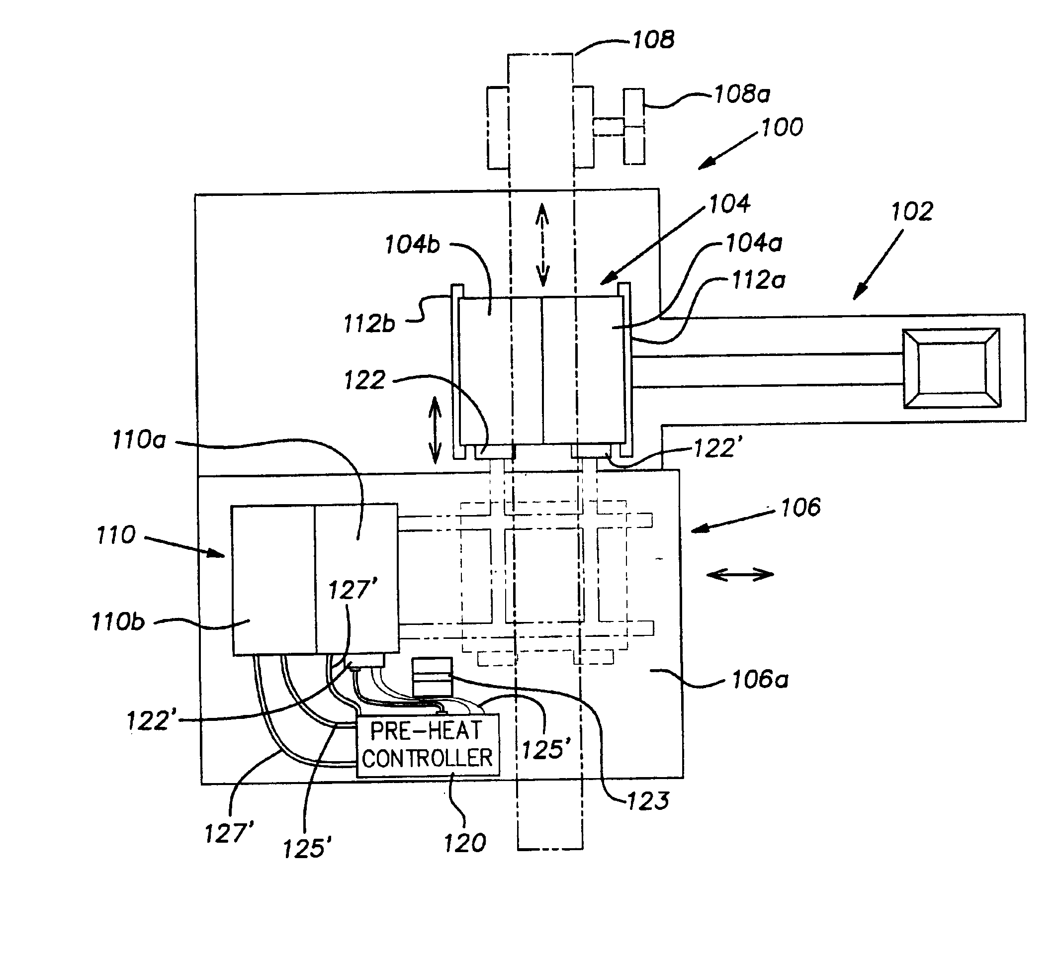
[0026]With reference to FIG. 3, an injection molding machine 100 according to the present invention is schematically illustrated. The injection molding machine includes an injector 102, a first die assembly 104 comprising a first fixed die 104a and a first movable die 104b, a die loading / unloading assembly 106 including a translatable mold transfer cart 106a, a part removal apparatus 108, and a second die assembly 110 comprising a second fixed die 110a and a second movable die 110b.

[0027]The first fixed die 104a is secured to a fixed die platan 112a, and the first movable die 104b is secured to a movable die platan 112b. The movable die platan 112b is moved relative to the fixed die 104a between a closed position and an open position. When the movable die platan 112b and associated movable die 104b are in the closed position, the first set of dies 104 is in position to mold a part. When the movable die platan 112b moves the movable die 104b to an open position, the molded part may ...


PUM

PropertyMeasurementUnit
timeaaaaaaaaaa
timeaaaaaaaaaa
timeaaaaaaaaaa

Abstract

A die preparation and exchange method wherein dies to be inserted into an injection molding machine are electrically and fluidly heated prior to insertion so as to prepare the dies to make parts more quickly. The die exchange sequence wherein a first set of dies are removed from the machine and are replaced by a second set of dies has been changed from a generally serial sequence to a sequence wherein most steps are performed in parallel or simultaneously, greatly reducing the downtime associated with mold change.

Description

BACKGROUND OF THE INVENTION[0001]1. Field of the Invention[0002]The present invention generally relates to plastic injection molding machines and, more particularly, toward improved methods for exchanging molds for use in injection molding machines.[0003]2. Description of Related Art[0004]Injection molding machines have developed over the years to permit molding of a variety of parts, from small, simple plastic parts to rather large and complex plastic parts. For large parts, such as automobile bumpers, the injection molding machines and resulting injection molding dies are correspondingly large and heavy.[0005]Due to the relatively short mold cycle time as compared to the rest of the factory, when using such large injection molding machines in a modern manufacturing environment, it is common to mold a particular part for a period of time with the first set of dies and then to exchange the first set of dies with a second set of dies to permit a different part to be molded. By switch...

Claims


Application Information

Patent Timeline
Patent Type & Authority Patents(United States)
IPC IPC(8): B29C45/73B29C45/17B29C31/00
CPCB29C45/73B29C45/1756B29C31/006
Inventor HUGHES, ALANOGURA, SOTORUPRYOR, ERICALLISON, TEDWILLIAMS, ROGER
Owner HONDA MOTOR CO LTD
Why Eureka
Try Eureka