Device for air cleaning from dust and aerosols

Inactive Publication Date: 2005-05-17
KOTLYAR GENNADY MIKHAILOVICH +1
View PDF5 Cites 20 Cited by
  • Summary
  • Abstract
  • Description
  • Claims
  • Application Information

AI Technical Summary

Benefits of technology

[0008]One advantage of the present invention is a device which purifies air by removing dust and aerosols.
[0009]Another advantage of the present invention is the ability to saturate the air with aromatic and medical substances.
[0010]Still another advantage of the present invention is its ease of use and greater application for complex air treatment.
[0011]These advantages are incorporated in a device for air purification by removing dust and aerosols comprising a body with an air inlet, disposed inside said body are corona and collecting electrodes having opposite polarities, deflecting electrodes behind which an electrode-generator of negatively charged electrons is mounted. Said generator is electrically coupled with precipitation electrodes. In the body a vessel for holding aromatic and medical substances is mounted. A reflector of positively charged electrons is mounted in front of the corona forming electrode. The reflector is electrically coupled with the corona-forming electrodes, while the means for distributing aromatic or medical substances includes one or more tapes made of porously-fiber material whose ends are placed within the vessel containing the aroma or medical substances being mounted beyond the body.
[0012]The proposed device allows for the removal of harmful positively charged aeroions. Additionally, it is not necessary to clean any dust from the reflector. Direct measurements have shown that concentrations of positively charged aeroions at the inlet are decreased to tens of

Problems solved by technology

The above-mentioned known device does not avoid extraction of harmful positively charged aeroions.
Additionally, the system does not provide for saturation of cleaned air with molecules of aromatic or medical substances if necessary.
This layer of dust partially neutralizes positively charged electrodes but mainly decreases the efficiency of the passive electrode as a precipitator of positively charged aeroions.
Therefore, it becomes necessary to

Method used


Image

  • Device for air cleaning from dust and aerosols
  • Device for air cleaning from dust and aerosols
  • Device for air cleaning from dust and aerosols

Examples


Embodiment Construction

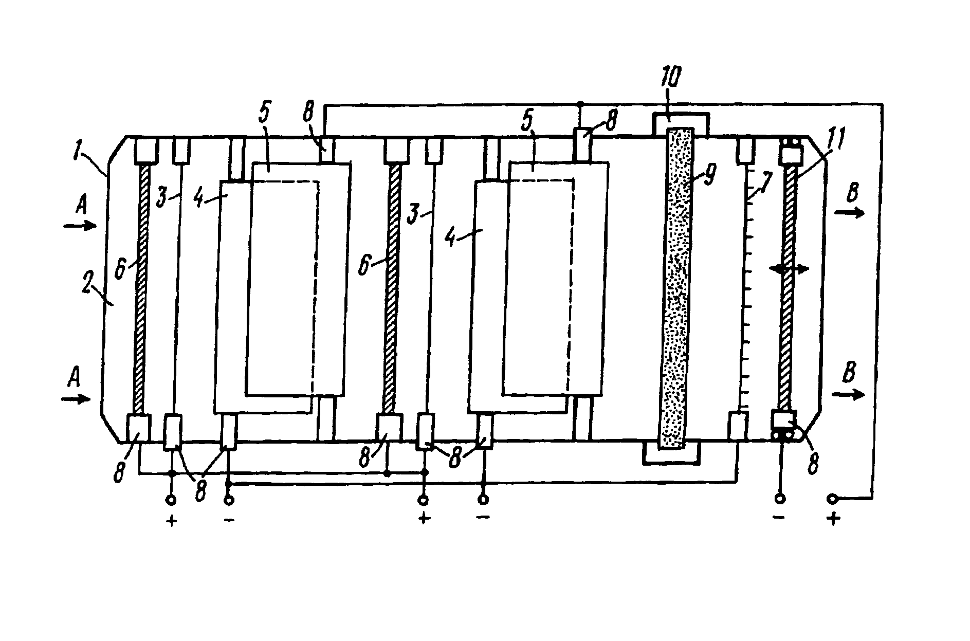
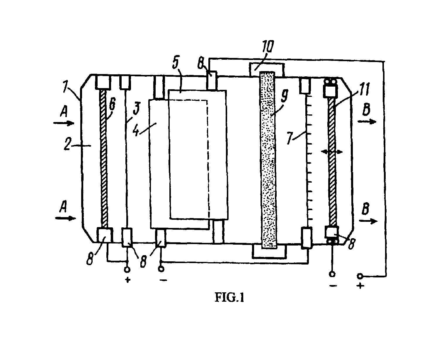
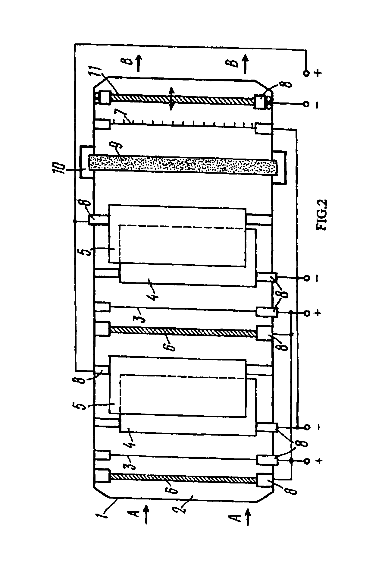
[0019]The proposed device comprises a body 1 (FIG. 1) with valve 2 for air, said valve having inlet and outlet (not shown in FIG. 1). Air enters the device through valve 2, shown in FIG. 1 by means of “A” arrow, while air output is shown by means of “B” arrow. Inside the body corona-forming electrodes 3 (positively charged) and precipitation electrodes 4 (negatively charged), as well as deflecting electrodes 5 (positively charged). Voltage volume supplied to the deflecting electrode 5 is less than voltage volume supplied to the corona-forming electrodes 3 and precipitation electrodes 4. In front of, and parallel to, corona-forming electrodes 3, a reflector of positively charged aeroions is placed at a distance. The reflector includes electrodes 6 electrically coupled with electrodes 3, electrodes 6 having bigger diameter than that of electrodes 3.

[0020]Behind deflection electrodes 5 an electrode-generator 7 of negatively charged aeroions is established, being electrically coupled wi...


PUM


Abstract

A device for air cleaning from dust and aerosols based on the use of non-homogeneous electrostatic field creating a flow of charged particles (the so called “ionic wind”) and operating as electrostatic precipitator. The device comprises a body inside which corona-forming and precipitation electrodes with opposite polarities are established. Inside the body deflection electrodes are established as well, in front of corona-forming electrodes a reflector for positively charged aeroions by an electrode electrically coupled with said corona-forming electrodes being established. The device comprises one or several tapes made of porous-fiber material placed into non-homogeneous electric field.

Description

CROSS-REFERENCE TO RELATED DISCLOSURE[0001]The present application is a U.S. National Stage application claiming the benefit of prior filed International Application, serial number PCT / RU01 / 00247, filed Jun. 21, 2001, which International Application claims a priority date of Mar. 27, 2001 based on prior filed Russian Application serial number RU2001 / 107867.TECHNICAL FIELD[0002]The present invention relates to separation of disperse particles with the use of an electrostatic effect, to be more precise, the present invention relates to devices aimed at cleaning dust and aerosols from the air. The invention has applications in all fields of industry as well as in domestic rooms.BACKGROUND ART[0003]One device contained in the prior art comprises a body with an air inlet and corona-forming and precipitation electrodes of opposite polarities. An electrostatic precipitation element is installed near the precipitation electrodes. The electrostatic precipitation element comprises two metal n...

Claims


Application Information

Patent Timeline
IPC IPC(8): A61L9/22B03C1/02B03C1/28B03C3/00B03C3/019B03C3/38B03C3/36B03C3/04B03C3/34B03C3/12F24F3/16
CPCA61L9/22B03C1/28B03C3/36B03C3/12B03C3/019Y02A50/2351B03C3/00
Inventor KOTLYAR, GENNADY MIKHAILOVICHSYSOEV, IVAN VASILIEVICH
Owner KOTLYAR GENNADY MIKHAILOVICH
Why Eureka
Try Eureka