Thermoelectric module

a technology of thermoelectric modules and modules, applied in the direction of thermoelectric devices, indirect heat exchangers, lighting and heating apparatus, etc., can solve the problems of requiring very high cost and above-mentioned art, and achieve the effect of efficient heat transmission, simple structure and less breakag

Inactive Publication Date: 2005-05-17
KOMATSU LTD
View PDF11 Cites 51 Cited by
  • Summary
  • Abstract
  • Description
  • Claims
  • Application Information

AI Technical Summary

Benefits of technology

[0009]The present invention is made in view of the above-described problems, and has its object to provide a thermoelectric module with a simple structure and with less breakage by thermal stress.
[0010]In order to attain the above-described object, a first aspect of the thermoelectric module according to the present invention includes p-type and n-type thermoelectric elements which are alternately placed, and outer electrodes and inner electrodes which are alternately placed between the thermoelectric elements, and at least part of at least either one of the outer electrode or the inner electrode has a shape approximately along an object which exchanges heat with the electrodes. According to this constitution, it is extremely easy to make the shape of the electrode along the shape of the object as compared with conforming the shape of the thermoelectric element to the shape of the object. As a result, heat is efficiently transmitted, and the efficiency of the thermoelectric module is enhanced.
[0011]A second aspect of the thermoelectric module according to the present invention includes p-type and n-type thermoelectric elements which are alternately placed, and outer electrodes and inner electrodes which are alternately placed between the thermoelectric elements, and the inner electrodes surround an object which exchanges heat with the electrodes. According to the constitution, heat of the object can be efficiently transmitted to the electrode from its circumference, and the efficiency of the thermoelectric module is enhanced.

Problems solved by technology

However, the aforementioned prior arts have the problems that will be described as follows.
Such ring-shaped thermoelectric elements 113 and 114 need to be produced by a special order, which requires very high cost.

Method used


Image

  • Thermoelectric module
  • Thermoelectric module
  • Thermoelectric module

Examples


first embodiment

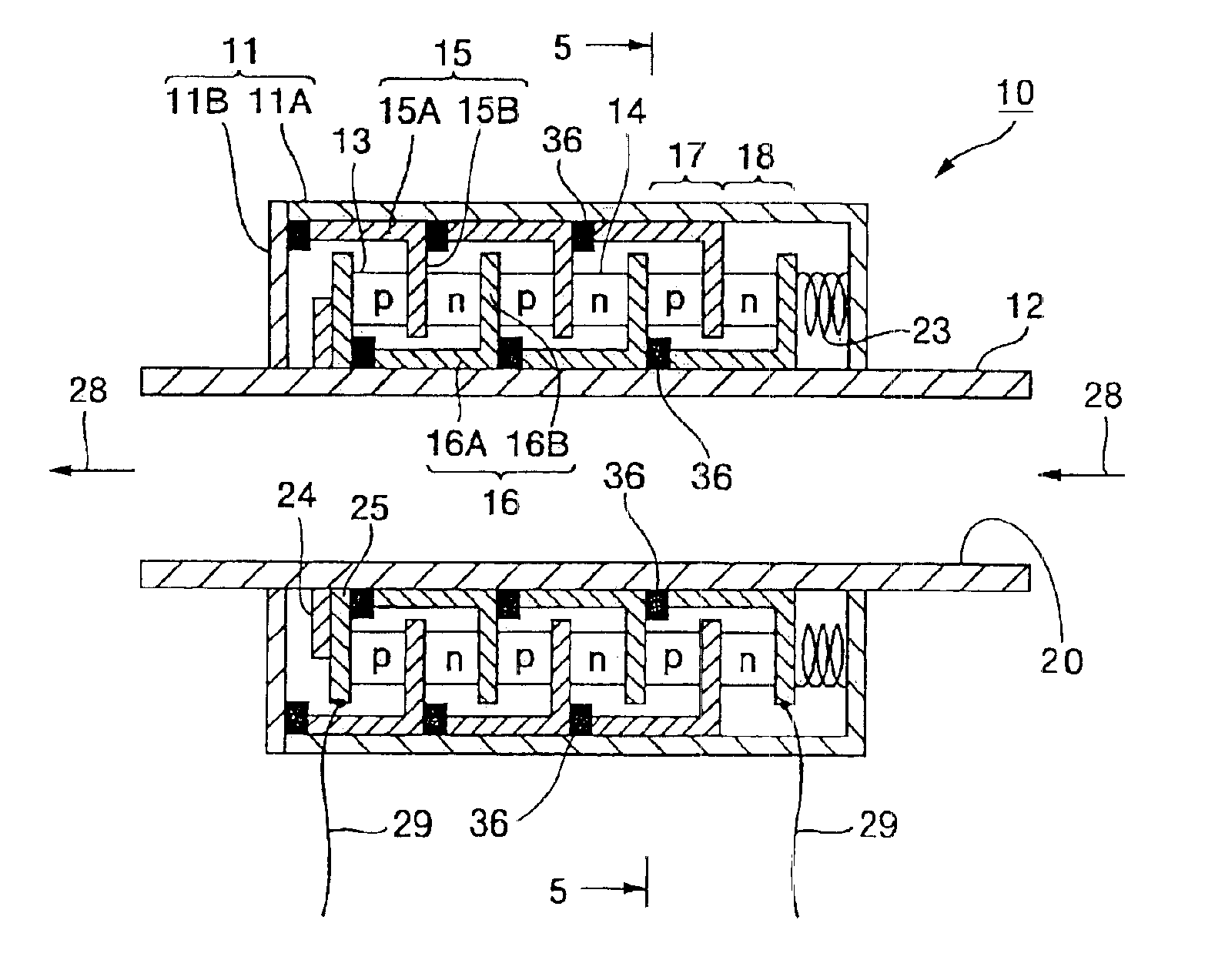
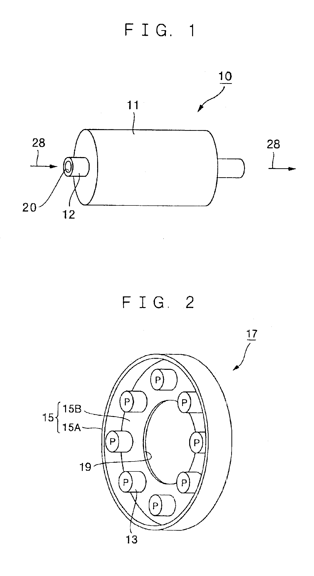
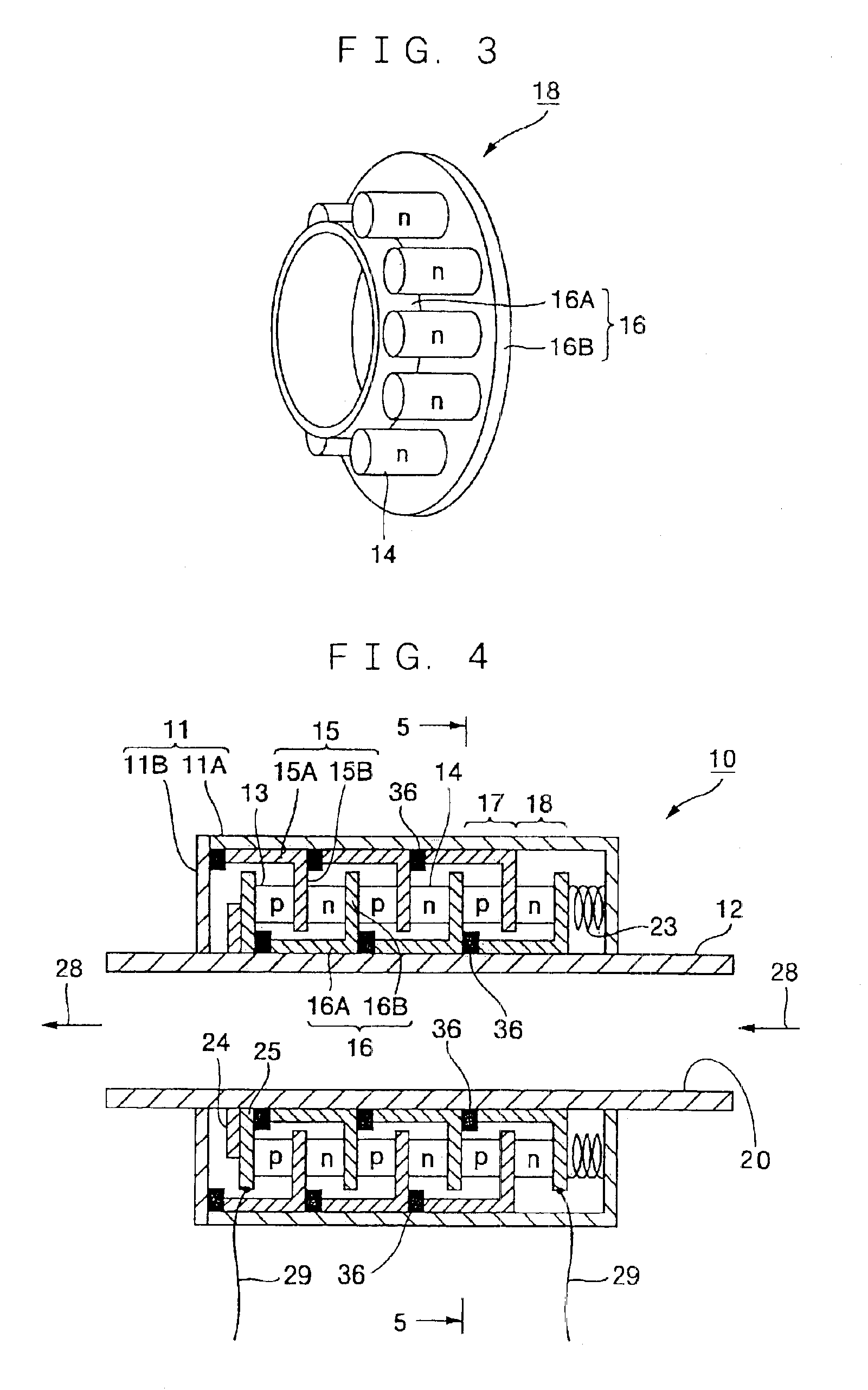
[0051]A first embodiment will be explained at first. FIG. 1 shows an external view of a thermoelectric module 10 according to the embodiment. In FIG. 1, the thermoelectric module 10 includes a hollow cylindrical pipe 12, and a hollow housing 11 with the pipe 12 being fitted in substantially a center part thereof. Thermoelectric elements that will be described later and electrodes are placed in a space between the housing 11 and the pipe 12. In the power generation type thermoelectric module 10, electromotive power is generated by thermal energy of an exhaust gas 28 passing through an inside of the pipe 12 to perform power generation. In a temperature adjustment type thermoelectric module, temperature adjustment of fluid passing through the inside of the pipe 12 is performed.

[0052]FIG. 2 shows a block diagram of a p-type thermoelectric unit 17 which combines the p-type thermoelectric elements 13 and an outer electrode 15. The outer electrode 15 is in a shape of a tea caddy with only ...

seventh embodiment

[0077]Namely, a flow path 20 is formed by the inner heat transfer plate 16A of the inner electrode 16 without fitting the pipe 12 in an inside, and fluid such as the exhaust gas 28 is passed into the inside, for example. As a result, heat is directly transferred between the fluid and the inner heat transfer plate 16A without interposing the pipe 12 between them, thus enhancing the heat transfer efficiency. Instead of feeding the fluid into the flow path 20, the solid rod 38 may be fitted into the inside as in the

[0078]A ninth embodiment will be explained. FIG. 20 shows a sectional front view of the thermoelectric module 10 in the ninth embodiment. In FIG. 20, the thermoelectric module 10 is molded by charging a mold material 39 such as silicon rubber with insulation properties around the thermoelectric elements 13 and 14 of the thermoelectric module as shown in FIG. 16, for example. Consequently, heat releasing from the surfaces of the thermoelectric elements 13 and 14 is reduced, t...


PUM


Abstract

A thermoelectric module with a simple structure with less breakage by thermal stress is provided. For this purpose, the thermoelectric module includes p-type and n-type thermoelectric elements (13, 14) which are alternately placed, and outer electrodes (15) and inner electrodes (16), which are alternately placed between the thermoelectric elements (13, 14), and at least part of at least either one of the outer electrode (15) or the inner electrode (16) has a shape approximately along an object which exchanges heat with the electrodes (15, 16). The inner electrodes (16) surround an object which exchanges heat with the electrodes (15, 16).

Description

TECHNICAL FIELD[0001]The present invention relates to a thermoelectric module.BACKGROUND ART[0002]Conventionally, cylindrical thermoelectric modules to perform power generation by utilizing exhaust heat of exhaust pipes of automobiles, boilers and the like to recover energy are known. For example, the one disclosed in Japanese Patent Laid-open No. 61-254082 is called a first prior art. FIG. 36 shows a thermoelectric module disclosed in the same Laid-open Patent, and the first prior art will be explained below based on FIG. 36. In FIG. 36, a thermoelectric module 110 includes a hollow pipe 112 being an inner cylinder and a housing 111 being an external cylinder. P-type and n-type thermoelectric elements 113 and 114 are alternately placed in a circumferential direction between the pipe 112 and the housing 111.[0003]First end portions of the thermoelectric elements 113 and 114 are connected by an inner electrode 116, and the inner electrode 116 is in contact with a pipe 112 via an insu...

Claims


Application Information

Patent Timeline
Patent Type & Authority Patents(United States)
IPC IPC(8): H01L35/28H01L35/30
CPCH01L35/30H10N10/13H10N10/17
Inventor AKIBA, HIRONORI
Owner KOMATSU LTD
Why Eureka
Try Eureka