
Stator arrangement of rotary electric machine

a rotary electric machine and frame technology, applied in the direction of windings, magnetic circuit shapes/forms/construction, solid insulation, etc., to achieve the effect of reducing the draft resistance of cooling air, improving cooling performance, and efficient discharging of foreign particles from the pair of frames

Inactive Publication Date: 2005-05-17
DENSO CORP
View PDF32 Cites 21 Cited by
  • Summary
  • Abstract
  • Description
  • Claims
  • Application Information

AI Technical Summary

Benefits of technology

This solution prevents electrolyte and foreign particle ingress, enhances insulation stability, reduces the risk of short-circuiting, and improves cooling efficiency by allowing easy adherence of insulation resin and maintaining a stable environment.

Problems solved by technology

Although temperature of the joint of winding and its vicinities becomes high while welding, foreign particles or electrolyte would not stay because no insulation film, which may be deteriorated by high temperature, exists there.

Method used


Image

  • Stator arrangement of rotary electric machine
  • Stator arrangement of rotary electric machine
  • Stator arrangement of rotary electric machine

Examples


Embodiment Construction

[0027]A vehicle AC generator according to a preferred embodiment of the invention is described in detail with reference to the appended drawings.

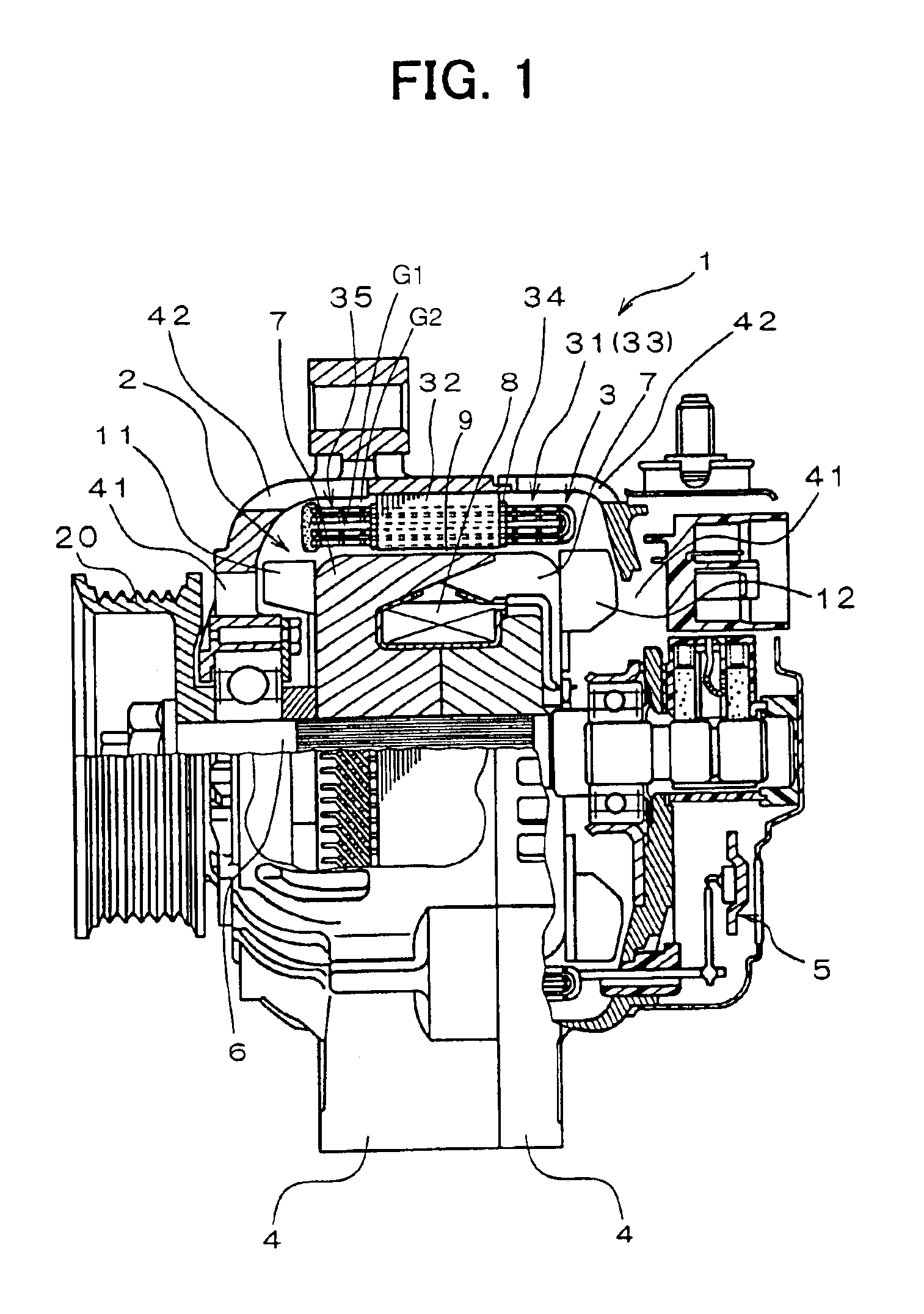
[0028]As shown in FIG. 1, the vehicle AC generator 1 according to the preferred embodiment is comprised of a rotor 2, a stator 3, a pair of frames 4, a rectifier unit 5, etc.

[0029]The rotor 2 is comprised of a field coil 8 having a cylindrically wound insulation-film-coated copper wire, a pair of pole cores 7, each having six craw poles, and a shaft 6. The shaft 6 penetrates the field coil 6 and the pair of claw poles. The claw poles envelop the field coil 8 from opposite ends thereof. A mixed-flow-type cooling fan 11 is welded to the front end of the pole core 7 to blow air from the front end in the axial and radial directions. A centrifugal cooling fan 12 is also welded to the rear end of the pole core 7 to blow air from the rear end in the radially outer direction.

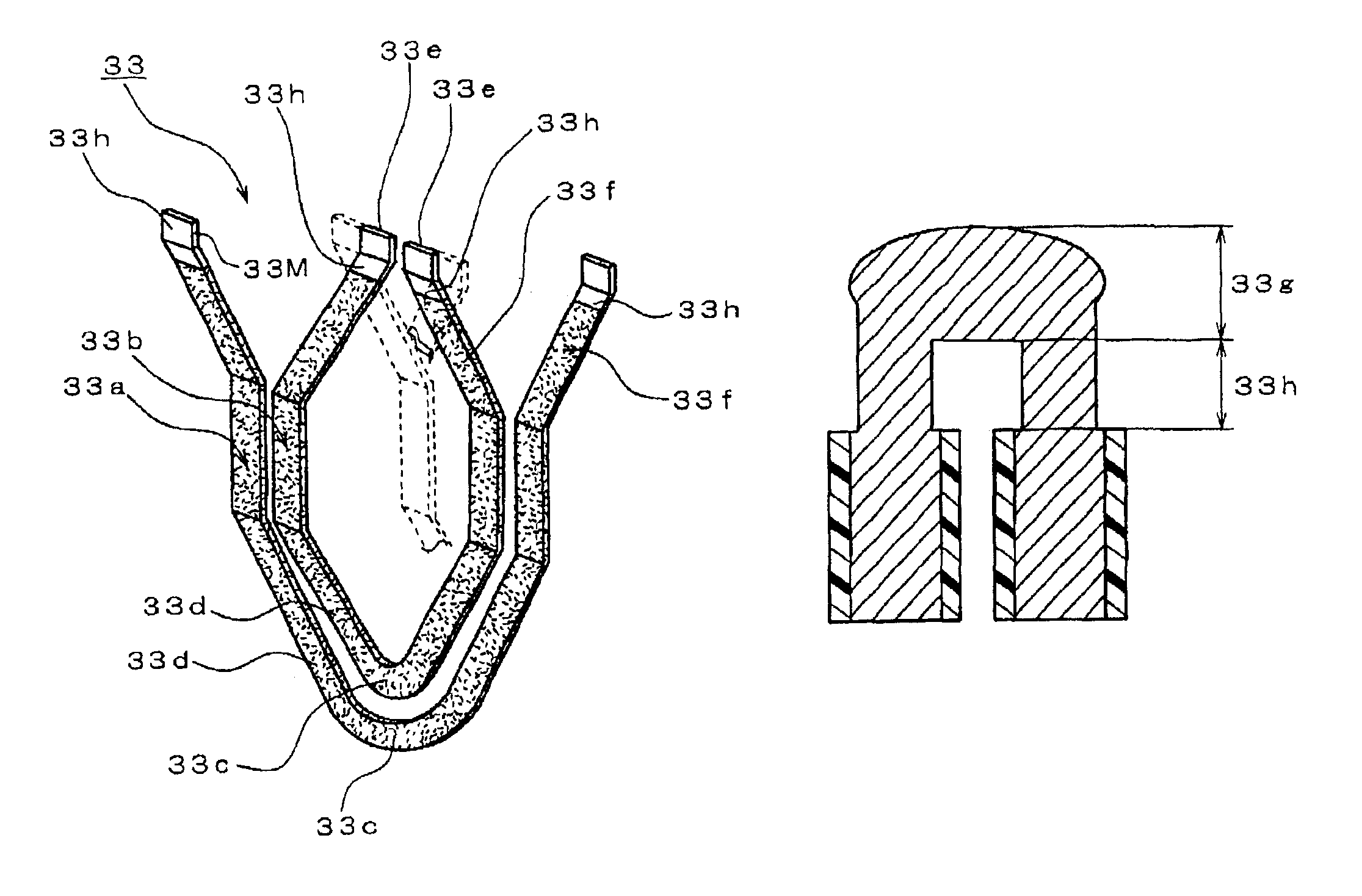
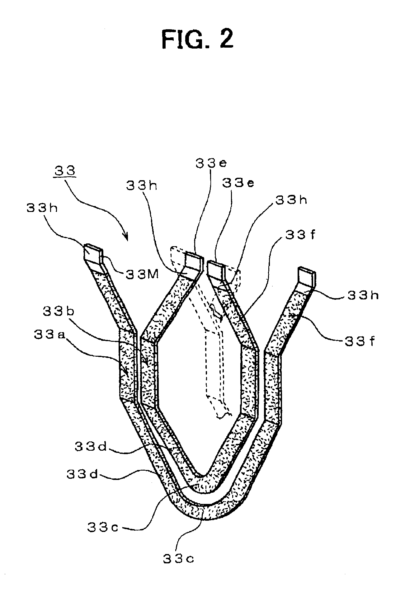
[0030]The stator 3 is comprised of a stator core 32, a stator winding 31 t...


PUM

PropertyMeasurementUnit
radial lengthaaaaaaaaaa
idling rotation speedaaaaaaaaaa
weightaaaaaaaaaa

Abstract

A vehicle rotary electric machine includes a rotor, a stator having a stator core and a stator winding mounted in the stator core and a pair of frames for supporting the rotor and the stator. The stator winding has a plurality of conductor segments coated with insulation film. Each of the conductor segments has segment ends that are circumferentially aligned and form two or more rings. The segment ends that contact each other are welded and form joints of winding that have a bare surface. Therefore, electrolyte or foreign particles are prevented from staying at otherwise deteriorated insulation film.

Description

CROSS REFERENCE TO RELATED APPLICATION[0001]The present application is based on and claims priority from Japanese Patent Application 2000-337847, filed Nov. 6, 2000, the contents of which are incorporated herein by reference.BACKGROUND OF THE INVENTION[0002]1. Field of the Invention[0003]The present invention relates to a vehicle rotary electric machine for a passenger car, a truck, etc.[0004]2. Description of the Related Art[0005]Recently, in order to solve environmental problems, various efforts to reduce idling rotation speed of a vehicle and vehicle weight for improving fuel consumption, and to narrow the engine compartment for increasing the passenger compartment have been made. As a result, the vehicle rotary electric machine that is driven by an engine has been required to reduce the size and to increase the output power thereof. In order to meet the above requirement, U.S. Pat. No. 5,998,903 or its basic application, JP-A-2000-69729, discloses a vehicle AC generator. In this...

Claims


Application Information

Patent Timeline
Patent Type & Authority Patents(United States)
IPC IPC(8): H02K3/38H02K3/12H02K15/00H02K3/32H02K19/22
CPCH02K3/12H02K3/38H02K15/0081H02K15/0056Y10T29/49009Y10T29/49073H02K19/22
Inventor KOIKE, AKIHITO
Owner DENSO CORP
Learn More