Luminary control system

a control system and light source technology, applied in semiconductor lasers, lighting and heating equipment, instruments, etc., can solve the problems of increasing the cost and complexity of light sources, and the instability of the feedback system

Active Publication Date: 2005-05-17
AVAGO TECH INT SALES PTE LTD
View PDF6 Cites 107 Cited by
  • Summary
  • Abstract
  • Description
  • Claims
  • Application Information

AI Technical Summary

Benefits of technology

[0005]The present invention includes a light source and method for controlling the same. The light source utilizes a light generator that generates a first light signal of a first wavelength at a first intensity that is set by a first control signal. A light monitor generates a first monitor signal having an amplitude determined by the first intensity. A target signal generator generates a first target signal having an amplitude indicative of a first target value. A difference circuit generates a first error signal having a magnitude related to the difference of the amplitudes of the first monitor signal and the first target signal. A feedback controller generates the first control signal in response to the first error signal. An initial control signal generator that causes the feedback controller to generate a preliminary first control signal in place of the first control signal, the preliminary control signal is independent of the first error signal and is generated for a first time period after the first target value changes to a new first target value. In one embodiment, the preliminary first control signal depends on the new first target value. In another embodiment, the first control signal includes a periodic signal that switches between a first value that causes the light generator to generate light of the first wavelength and a second value at which the light generator does not generate light of the first wavelength. The feedback controller varies the fraction of time at which the first control signal is at the first value. In another embodiment, the light monitor includes a photodetector and a low pass filter characterized by a delay time, and the first time period is set to a value greater than the delay time. Embodiments that include multiple light generators that generate light in different spectral bands can also be constructed to provide a color light source having an output color that can be controlled and rapidly changed.

Problems solved by technology

The low-pass filter introduces a delay in the feedback system that is sufficient to cause the feedback system to become unstable when the light source is switched between different colors in which one or more of the duty factors change by a large amount.
While such instabilities can be reduced by utilizing complex active filters, this solution increases the cost and complexity of the light source.

Method used


Image

  • Luminary control system
  • Luminary control system
  • Luminary control system

Examples


Embodiment Construction

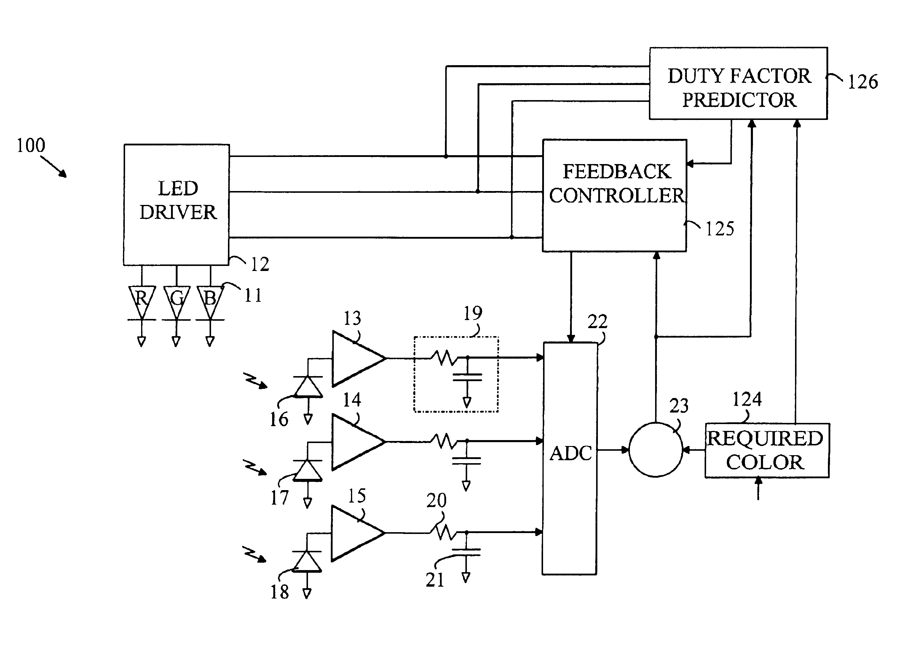
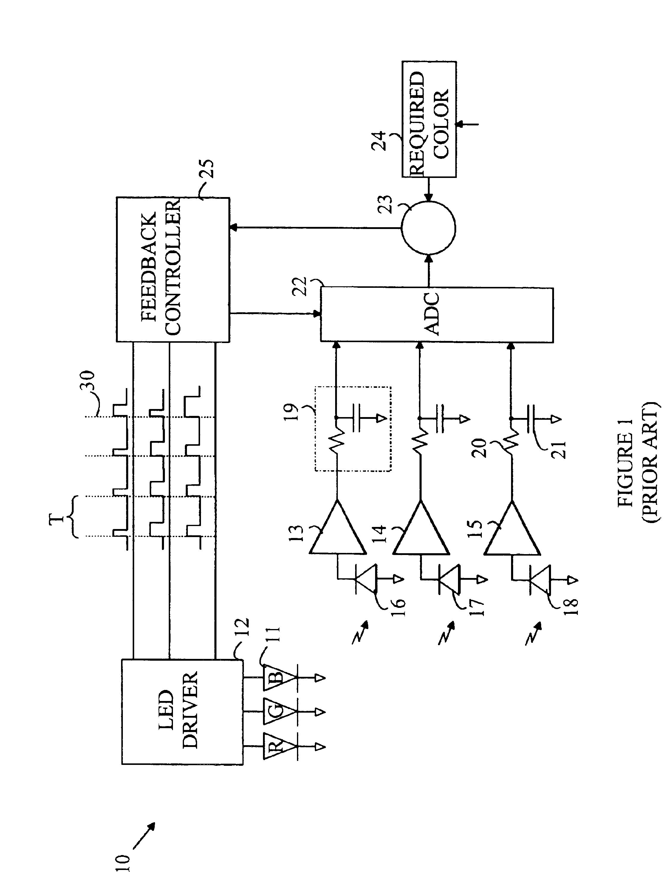
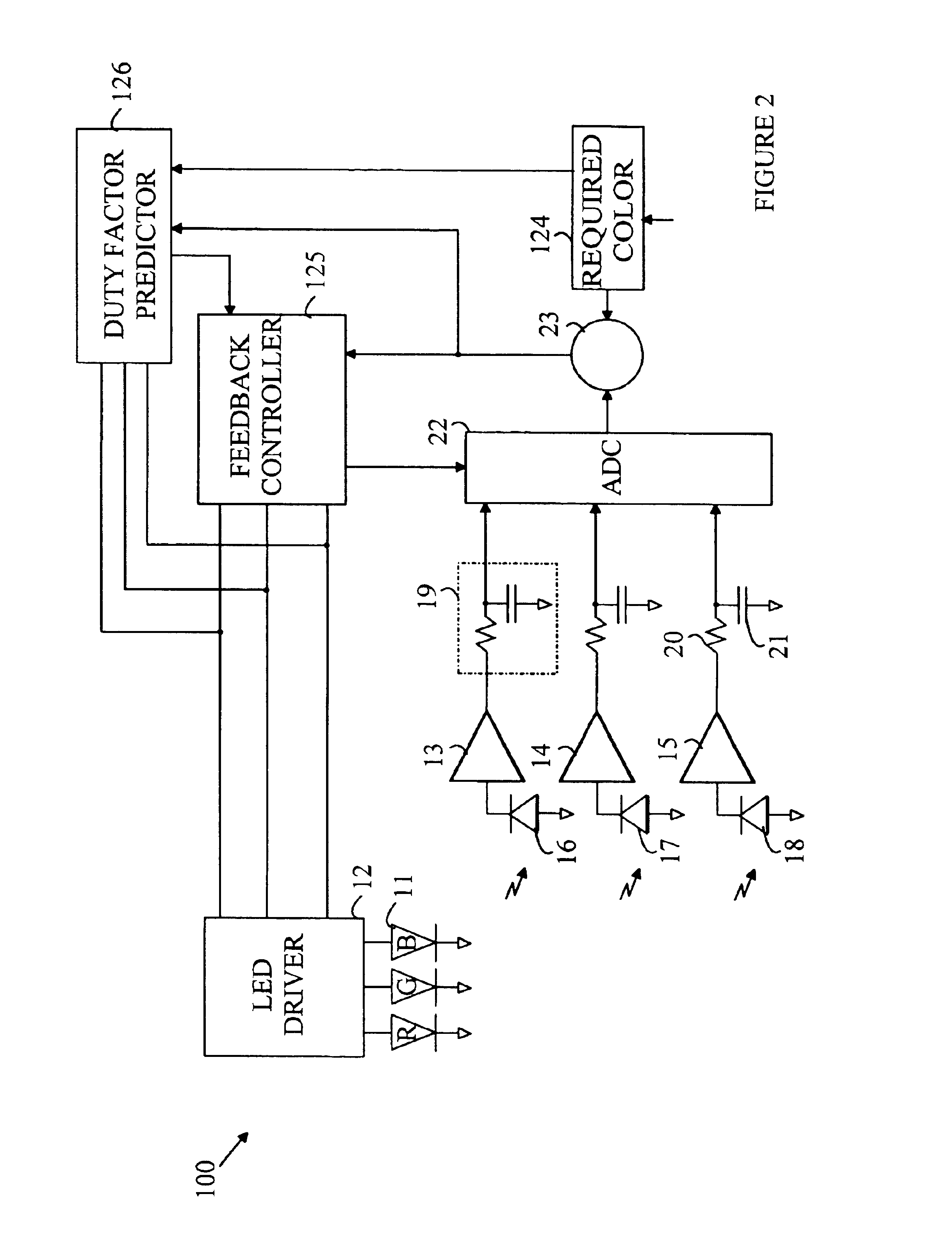
[0010]The manner in which the present invention provides its advantages can be more easily understood with reference to FIG. 1. FIG. 1 is a block diagram of a prior art LED light source that utilizes a feedback system to control the duty factor of the individual LEDs to produce a precise output color. Light source 10 utilizes red, green, and blue LEDs 11 to generate light of an arbitrary color. The LEDs are driven by a driver 12 that sets the current through each LED when that LED is “on”. In the “on” state, each LED is driven with a predetermined current that is independent of the color being generated by light source 10. The LEDs are driven in a pulsed manner with a cycle time having a period T. During each period, each of the LEDs is turned on for a time t that depends on the color of light that is to be generated by light source 10.

[0011]To simplify the following discussion the ratio t / T will be referred to as the duty factor. In principle, the intensity of the light, as seen by...


PUM


Abstract

A light source and method for controlling the same. The light source utilizes a light generator that generates a light signal of a wavelength at an intensity that is set by a control signal. The control signal is controlled by a servo that monitors the light output of the light generator and compares the monitored value with a target value. When the target value is changed, the control signal is initially replaced by a predicted control signal based on the new target value rather than the error signal generated in the servo. This provides time for the servo to adjust to the new target value. In one embodiment, the control signal includes a periodic signal that switches between a value that causes the light generator to generate light of the wavelength and a second value at which the light generator does not generate light of the wavelength.

Description

FIELD OF THE INVENTION[0001]The present invention relates to light sources.BACKGROUND OF THE INVENTION[0002]Light emitting diodes (LEDs) are attractive candidates for replacing conventional light sources such as incandescent lamps and fluorescent light sources. The LEDs have higher light conversion efficiencies and longer lifetimes. Unfortunately, LEDs produce light in a relatively narrow spectral band. Hence, to produce a light source having an arbitrary color, a compound light source having multiple LEDs is typically utilized. For example, an LED-based light source that provides an emission that is perceived as matching a particular color can be constructed by combining light from red, green, and blue emitting LEDs. The ratio of the intensities of the various colors sets the color of the light as perceived by a human observer.[0003]One method of varying LED intensity is to vary the amount of time the LED is turned on. In such schemes, the LED is pulsed on a time scale that is too ...

Claims


Application Information

Patent Timeline
Patent Type & Authority Patents(United States)
IPC IPC(8): F21V9/08F21V9/00G05D25/00G05D25/02G05F1/00H01L33/00H01S5/00H01S5/0683H05B37/02H05B37/00H05B33/02H05B33/08H05B44/00
CPCH05B33/0818H05B33/086H05B33/0869H05B33/0863Y10S315/04Y02B20/346H05B45/22H05B45/325G05D25/02H05B47/10H05B44/00Y02B20/30
Inventor LIM, KEVIN LILEE, JOON CHOKJAFFAR, RIZAL BIN
Owner AVAGO TECH INT SALES PTE LTD
Why Eureka
Try Eureka