Method and device for correcting organ motion artifacts in MRI systems

a technology of organ motion and mri, applied in the field of magnetic resonance imaging, can solve the problems of impede diagnosis, relative long orderly data acquisition time, blurring and replication of reconstructed images,

Inactive Publication Date: 2005-05-17
HER MAJESTY THE QUEEN AS REPRESENTED BY THE MINIST OF NAT DEFENCE OF HER MAJESTYS CANADIAN GOVERNMENT
View PDF5 Cites 35 Cited by
  • Summary
  • Abstract
  • Description
  • Claims
  • Application Information

AI Technical Summary

Benefits of technology

[0042]Through careful selection of the phases of the cardiac and respiratory cycles and corresponding ranges MRI data acquisition periods are of the order of seconds or a few minutes. Furthermore, integration of...

Problems solved by technology

One major disadvantage of the MRI is the relatively long data-acquisition time in order to produce high quality, diagnostically interpretable images.
Unfortunately, the duration of the data acquisition is long enough—of the order of a few seconds—for organ motion such as cardiac motion, respiration, blood flow, peristalsis or restlessness to cause artifacts such as blurring and replication—commonly termed as ghosting—in the reconstructed image.
As is evident, su...

Method used


Image

  • Method and device for correcting organ motion artifacts in MRI systems
  • Method and device for correcting organ motion artifacts in MRI systems
  • Method and device for correcting organ motion artifacts in MRI systems

Examples


first embodiment

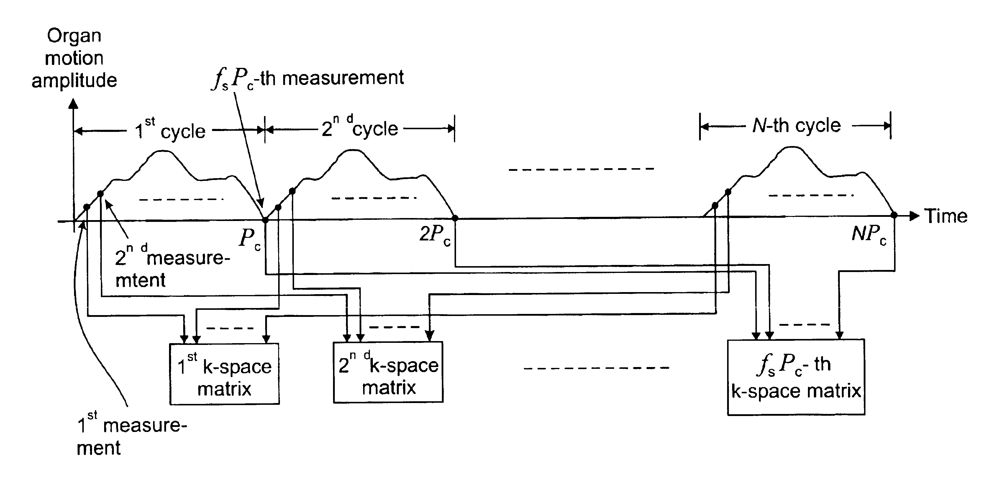
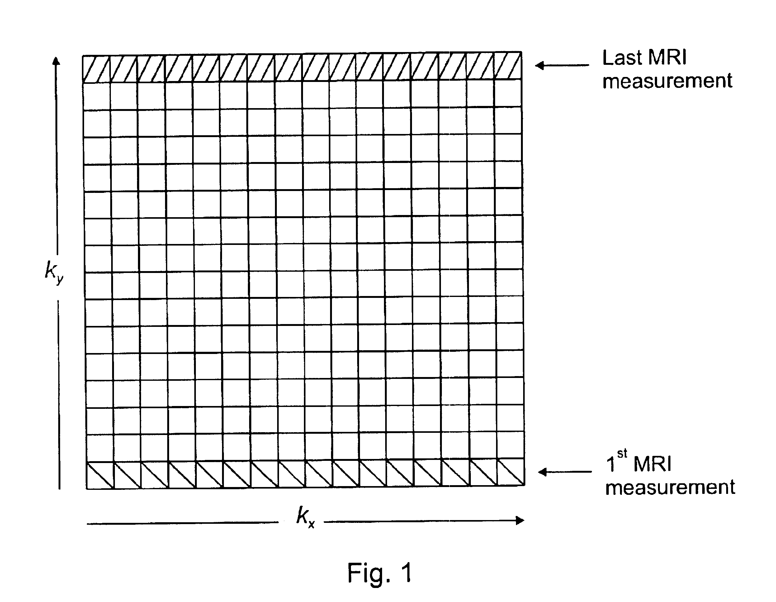
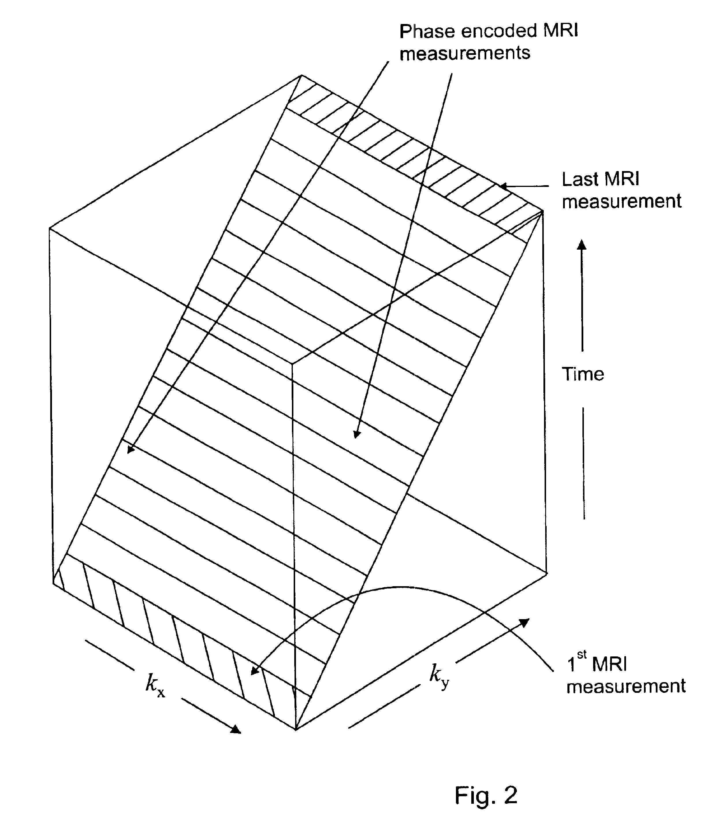
[0080]Referring to FIG. 11 a simplified flow diagram illustrating the principal processing steps of a method for correcting organ motion according to the invention is shown. A plurality of sets of the MRI measurement data indicative of at least an image of an object are received—box 10. Each set corresponds to one row kx of a k-space matrix of at least a k-space matrix. Upon receipt, for each set of the plurality of sets of the MRI measurements a k-space matrix of the at least a k-space matrix are determined for allocation thereto based on motion data indicative of the motion of the object occurring during acquisition of the plurality of sets of the MRI measurement data—box 12. In a following step, for each set of the plurality of sets of the MRI measurement data a location within the k-space matrix allocated thereto is determined—box 14. Based on the sets of the plurality of sets of the MRI measurement data allocated thereto at least a k-space matrix is generated—box 16. Inverse Fo...

second embodiment

[0082]For example, it is known that the cardiac frequency ƒecg can drift from its initially measured value during the MRI data acquisition process. Thus equation (4) is not satisfied even if the respiratory frequency ƒbreath remains the same. This limitation is overcome by the method for correcting organ motion according to the invention based on the coherent k-space synthesis which allows drifts and mismatches in the above mentioned physiological parameters. Here, instead of assuming a precise cardiac and respiratory frequency, a relative range of the phases of the heart and lung motion is determined as illustrated in FIGS. 14 and 15. Thus, if the heart and lung phases fall within the determined ranges, the measurements collected during these ranges are used for image reconstruction.

[0083]More specifically, the second embodiment of the method for correcting organ motion according to the invention comprises the following processing steps, as shown in the flow diagram of FIG. 16. Dur...

third embodiment

[0099]Referring to FIG. 19 a simplified flow diagram illustrating the principal processing steps of a method for correcting organ motion according to the invention is shown. A plurality of sets of the MRI measurement data indicative of at least an image of an object are received—box 50. Each set corresponds to one row kx of a k-space matrix of at least a k-space matrix. Further, motion data indicative of translational and rotational motion of a patient's head are received—box 52. The motion data are indicative of the patient's head motion during acquisition of the plurality of sets of the MRI measurements. Upon receipt, for each set of the plurality of sets of the MRI measurements a k-space matrix of the at least a k-space matrix is determined for allocation thereto based on the motion data—box 54. In a following step, for each set of the plurality of sets of the MRI measurement data a location within the k-space matrix allocated thereto is determined—box 56. Based on the sets of th...


PUM


Abstract

The present invention relates to a signal processing method and system for correcting organ motion artifacts for cardiac and brain imaging. A plurality of sets of MRI measurement data indicative of at least an image of an object is received. Each set corresponds to one row kx of a k-space matrix of at least a k-space matrix. For each set a k-space matrix of the at least a k-space matrix is determined for allocation thereto based on motion information of the object occurring during acquisition of the plurality of sets of the MRI measurement data. In a following step a location within the allocated k-space matrix corresponding to a row of the k-space matrix allocated thereto is determined for each set. At least a k-space matrix is then generated by re-arranging the plurality of sets. Each of the at least a k-space matrix comprises the sets of the plurality of sets of the MRI measurement data allocated thereto. Inverse Fourier transforming of the plurality of k-space matrices provides at least a reconstructed image. Through careful selection of the phases of the cardiac and respiratory cycles and corresponding ranges MRI data acquisition periods are of the order of seconds or a few minutes. Furthermore, integration of motion artifact free MRI images of different phases of organ motion using the coherent k-space synthesis according to the invention allows provision of an animation showing different phases of a cardiac or lung cycle. In an embodiment for correcting motion artifacts for brain imaging a motion vector describing translational and rotational motion of a patient's head is tracked during the MRI data acquisition process. The motion artifacts are then corrected based on coherent k-space synthesis using the motion vector data.

Description

[0001]This application claims benefit from U.S. Provisional Application No. 60 / 428,712 filed Nov. 25, 2002.FIELD OF THE INVENTION[0002]This invention relates to magnetic resonance imaging and in particular to signal processing methods and systems for correcting organ motion artifacts for cardiac and brain imaging.BACKGROUND OF THE INVENTION[0003]Magnetic resonance imaging (MRI) is a medical imaging tool that provides cross-sectional images or “slices” of a human body. Major advantages of the MRI compared to other medical imaging techniques are high contrast sensitivity to soft tissue differences, high spatial resolution, ease of 2-dimensional (2D) and 3-dimensional (3D) imaging and patient safety due to use of non-ionizing radiation. Therefore, the MRI is presently the primary choice for cross-sectional imaging of the human body over many CT / X-ray and other tomography imaging techniques. Recently, the MRI has experienced substantial improvements in image quality due to introduction ...

Claims


Application Information

Patent Timeline
IPC IPC(8): G01R33/567G01R33/54
CPCG01R33/5673G01R33/56325
Inventor STERGIOPOULOS, STERGIOSWROBEL, MIROSLAWFREIBERT, ANDREASYOUNIS, WAHEEDDHANANTWARI, AMAR
Owner HER MAJESTY THE QUEEN AS REPRESENTED BY THE MINIST OF NAT DEFENCE OF HER MAJESTYS CANADIAN GOVERNMENT
Why Eureka
Try Eureka