Method and system for determining DCT block boundaries

a dct block and boundary technology, applied in the field of digital image processing, can solve the problems of significant quality loss, block misalignment, multi-compression cycle introduction of additional quality degradation, etc., and achieve the effect of reliable dct block boundary determination and computational efficiency

Inactive Publication Date: 2005-05-17
MONUMENT PEAK VENTURES LLC
View PDF3 Cites 19 Cited by
  • Summary
  • Abstract
  • Description
  • Claims
  • Application Information

AI Technical Summary

Benefits of technology

[0011]The present invention provides a method for reliably determining the DCT block boundaries of decompressed JPEG and MPEG images, regardless of the degree of compression that has been applied to the images. The method is also computationally efficient.

Problems solved by technology

Multiple compression cycles can introduce additional quality degradations, even if the same compression parameters are used for each cycle.
However, block misalignment can occur when an image is cropped between compression cycles.
336-347, 1998, that a misalignment of the DCT blocks between compression cycles can lead to significant quality loss.
However, in some cases, only a decompressed image is available, and this decompressed image may have been cropped at some point in its processing history.
In such highly compressed images, severe quantization of the DCT coefficients leads to blocking artifacts as a result of the block-based nature of the 8×8 DCT.
However, these methods are suitable only when distinct and severe blocking artifacts are present in the decompressed image.
They will not work for determining the DCT block boundaries of cropped images at low to moderate compression levels, as described previously.

Method used


Image

  • Method and system for determining DCT block boundaries
  • Method and system for determining DCT block boundaries
  • Method and system for determining DCT block boundaries

Examples


Embodiment Construction

[0022]Because image processing systems employing JPEG and MPEG compression are well known, the present description will be directed in particular to attributes forming part of, or cooperating more directly with, system and methodology in accordance with the present invention. Attributes not specifically shown or described herein may be selected from those known in the art. In the following description, a preferred embodiment of the present invention would ordinarily be implemented as a software program, although those skilled in the art will readily recognize that the equivalent of such software may also be constructed in hardware. Given the system as described according to the invention in the following materials, software not specifically shown, suggested or described herein that is useful for implementation of the invention is conventional and within the ordinary skill in such arts.

[0023]If the invention is implemented as a computer program, the program may be stored in conventio...


PUM


Abstract

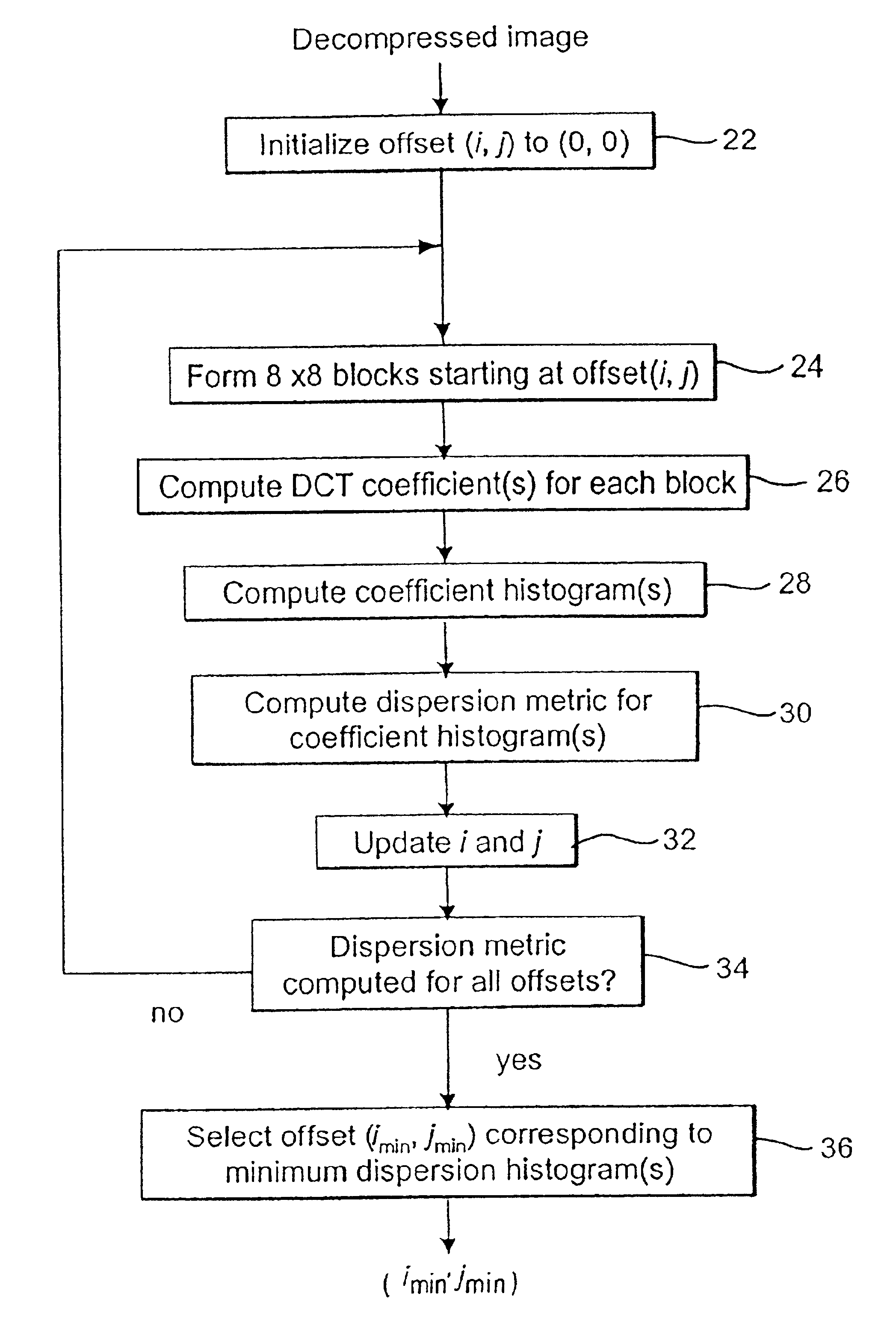
The horizontal and vertical offset for the M×N DCT block boundaries are determined for a decompressed image originally produced by a DCT-based compression system, regardless of the amount of compression and/or cropping that had been applied to the image. The method includes the steps of: a) computing one or more selected DCT coefficients from nonoverlapping, contiguous M×N blocks of the decompressed image, beginning at a selected offset; b) computing a coefficient histogram from a set of values for each selected DCT coefficient obtained from the blocks of the decompressed image; c) computing a dispersion metric from each coefficient histogram; d) repeating steps (a) through (c) for a plurality of offsets within an M×N block; e) comparing the dispersion metrics corresponding to the plurality of offsets to determine the minimum dispersion coefficient histogram; and f) selecting the offset that corresponds to the minimum dispersion coefficient histogram as the offset for the DCT block boundaries.

Description

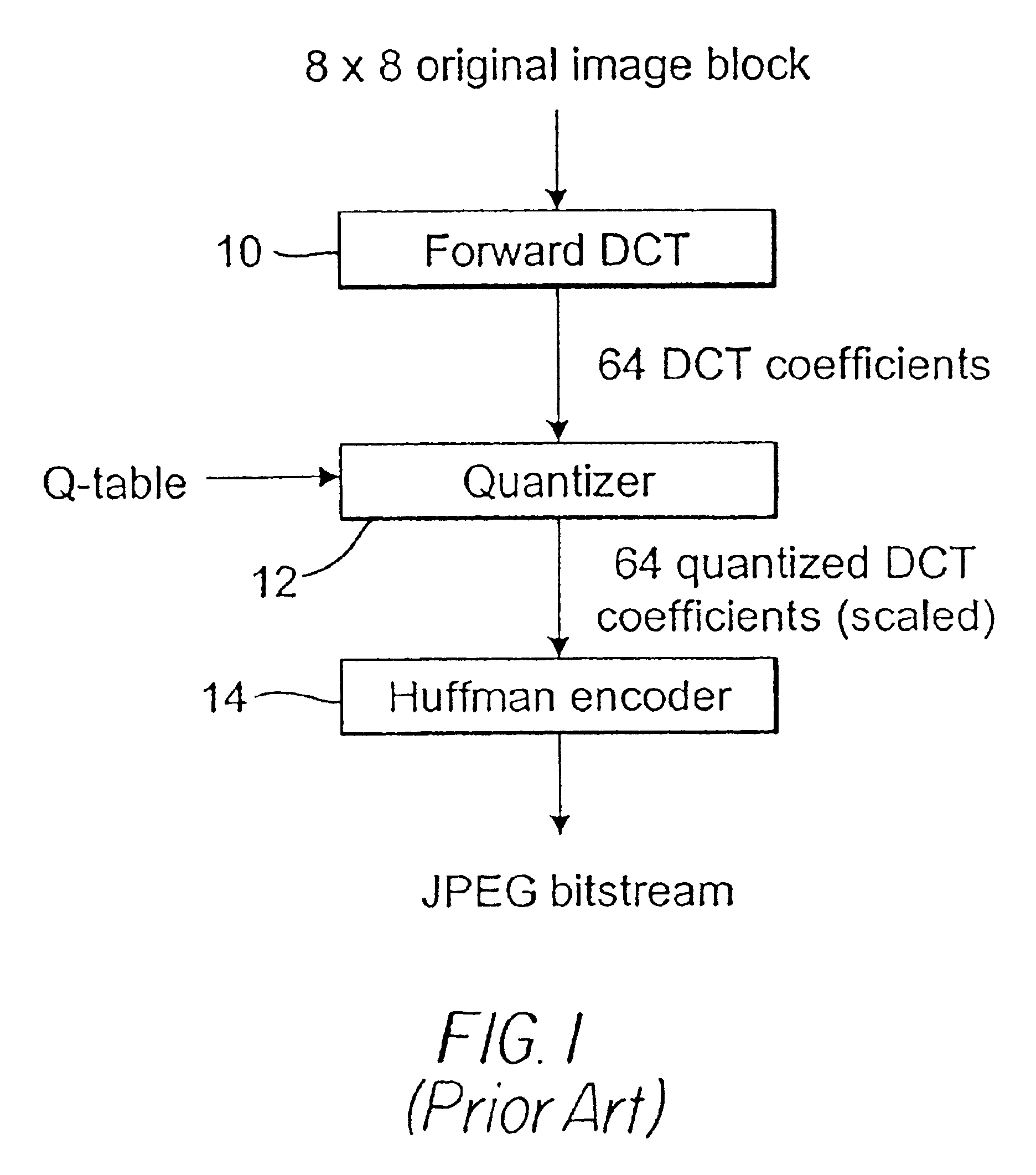
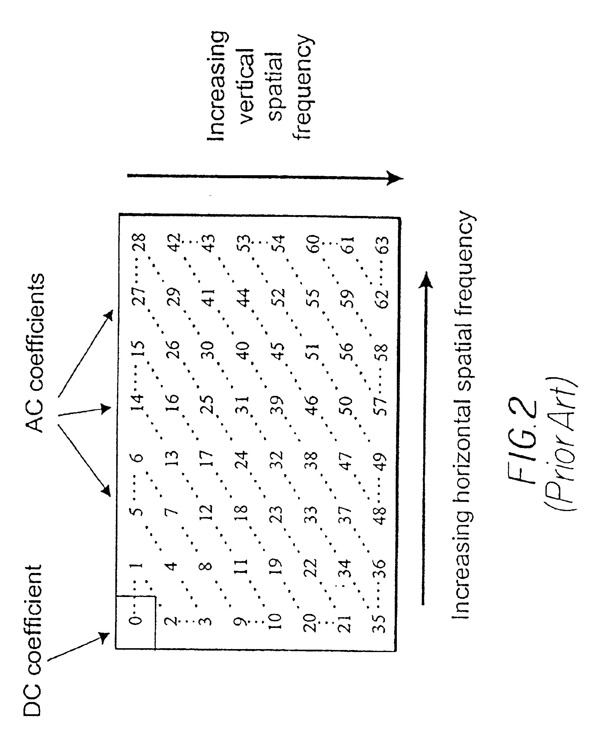
FIELD OF THE INVENTION[0001]The invention relates generally to the field of digital image processing, and in particular to a system for determining the DCT block boundaries in JPEG and MPEG-compressed images.BACKGROUND OF THE INVENTION[0002]The JPEG and MPEG international compression standards have been widely adopted for the efficient storage and transmission of still images and image sequences. A common aspect of these compression standards is that they use the discrete cosine transform (DCT) as a key component in the compression process. The DCT decomposes the original pixel values into a frequency domain representation (i.e., DCT coefficients), which can be quantized and efficiently encoded. Specifically, JPEG and MPEG apply the DCT to contiguous, nonoverlapping 8×8 blocks of pixels to produce 64 DCT coefficients for each block. Because the DCT coefficients are quantized, JPEG and MPEG are lossy compression methods, i.e., a compressed / decompressed image will not be identical to ...

Claims


Application Information

Patent Timeline
Patent Type & Authority Patents(United States)
IPC IPC(8): G06K9/00G06K9/46G06K9/36H04N7/26H04N7/30
CPCH04N19/86H04N19/60
Inventor JONES, PAUL W.RABBANI, MAJIDHOOVER, JOHN E.
Owner MONUMENT PEAK VENTURES LLC
Why Eureka
Try Eureka