
Interconnected broadcast and select optical networks with shared wavelengths

a wavelength-sharing, broadcasting technology, applied in the field of all optical networks, can solve the problems of lasing phenomenon, limited transmission distance and data rate, and wavelengths may circulate perpetually around the ring

Inactive Publication Date: 2005-05-17
SNELL HLDG LLC +2
View PDF16 Cites 48 Cited by
  • Summary
  • Abstract
  • Description
  • Claims
  • Application Information

AI Technical Summary

Benefits of technology

[0013]Accordingly, an object of the present invention is to provide an all optical network that eliminates all of the wavelength converters and regenerators between optical networks.
[0014]Another object of the present invention is to provide an all optical network that eliminates wavelength-dependent OADM's within an optical ring network.
[0015]A further object of the present invention is to provide a method for transmission in an optical network that uses a large number of wavelengths to eliminate the need for complicated OADM's, and to make the broadcast-and-select all-optical network architecture practically usable.
[0016]Another object of the present invention is to provide a method that uses a large number of wavelengths that are transmitted over a long distance to cover multiple interconnected optical networks to eliminate all of the wavelength converters and regenerators between optical networks and all of the wavelength-dependent OADMs within an optical ring network.
[0017]Another object of the present invention is to provide the combination of a dynamic wavelength-tunable optical transmitter and a dynamic wavelength-tunable receiver to ia simplify dynamic wavelength provisioning and configurability.
[0025]In another embodiment of the present invention, a method of transmitting optical ring traffic provides a broadcast-and-select optical network. A sufficient number of wavelengths are transmitted over a long distance in the optical network to eliminate wavelength converters and regenerators between rings in a network.

Problems solved by technology

Wavelength-converters are needed because conventional DWDM systems do not possess enough wavelengths to cover a wide service area such as multiple interconnected rings, and therefore wavelengths used in one ring must be re-used in another ring via wavelength converters.
Regenerators are needed because most of the transmission technologies used in today's metro networks can only support limited transmission distance and data rates.
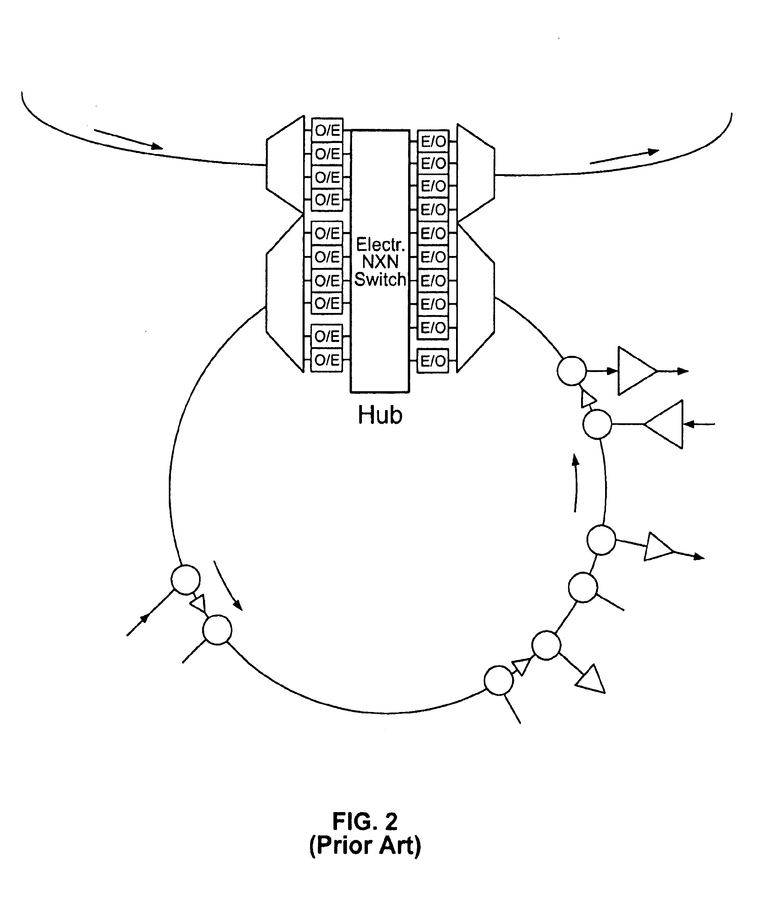
If the central hub in FIG. 2 does not terminate all the wavelengths by DWDM mux / demux and O-E-O regenerators, there is a possibility that the wavelengths may circulate perpetually around the ring especially when excessive amplifications are supplied along the ring.
This positive net gain can cause lasing phenomenon and consequently unstable received signals.
This method makes network control very complicated because adaptive loss control must be provided to different ring sizes and number of nodes, and the system bit-error-rate performance can be degraded.
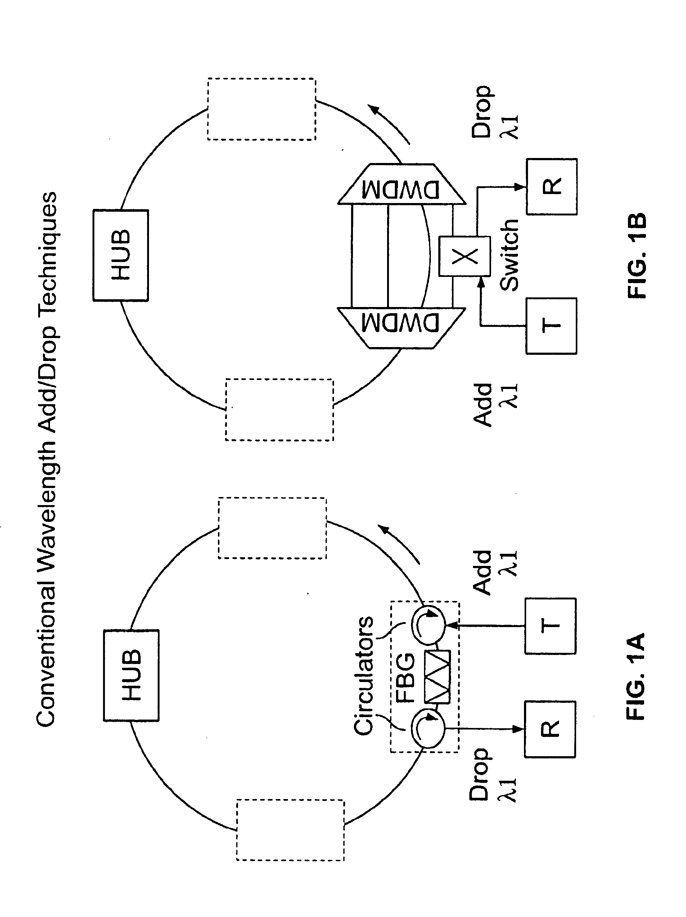
Consequently, when there are two or more wavelengths needed to be dropped, more FBGs are inserted between the two optical circulators, and service disruption is incurred.
This results in two problems, (1) once a fixed number of 2×2 switches are installed, future upgrade to install more switches can cause service disruptions, and (2) if an N×N switch is installed right at the beginning to cover every possible wavelength / band add-drop in the future, its cost will be high.
In addition, the N×N switch long-term reliability is still questionable.
In either case, the disadvantage is that no wavelength can be re-used.
Most of today's metro-ring optical networks have a limited number of available wavelengths, consequently one cannot afford not to “re-use” the “dropped” wavelengths.

Method used


Image

  • Interconnected broadcast and select optical networks with shared wavelengths
  • Interconnected broadcast and select optical networks with shared wavelengths
  • Interconnected broadcast and select optical networks with shared wavelengths

Examples


Embodiment Construction

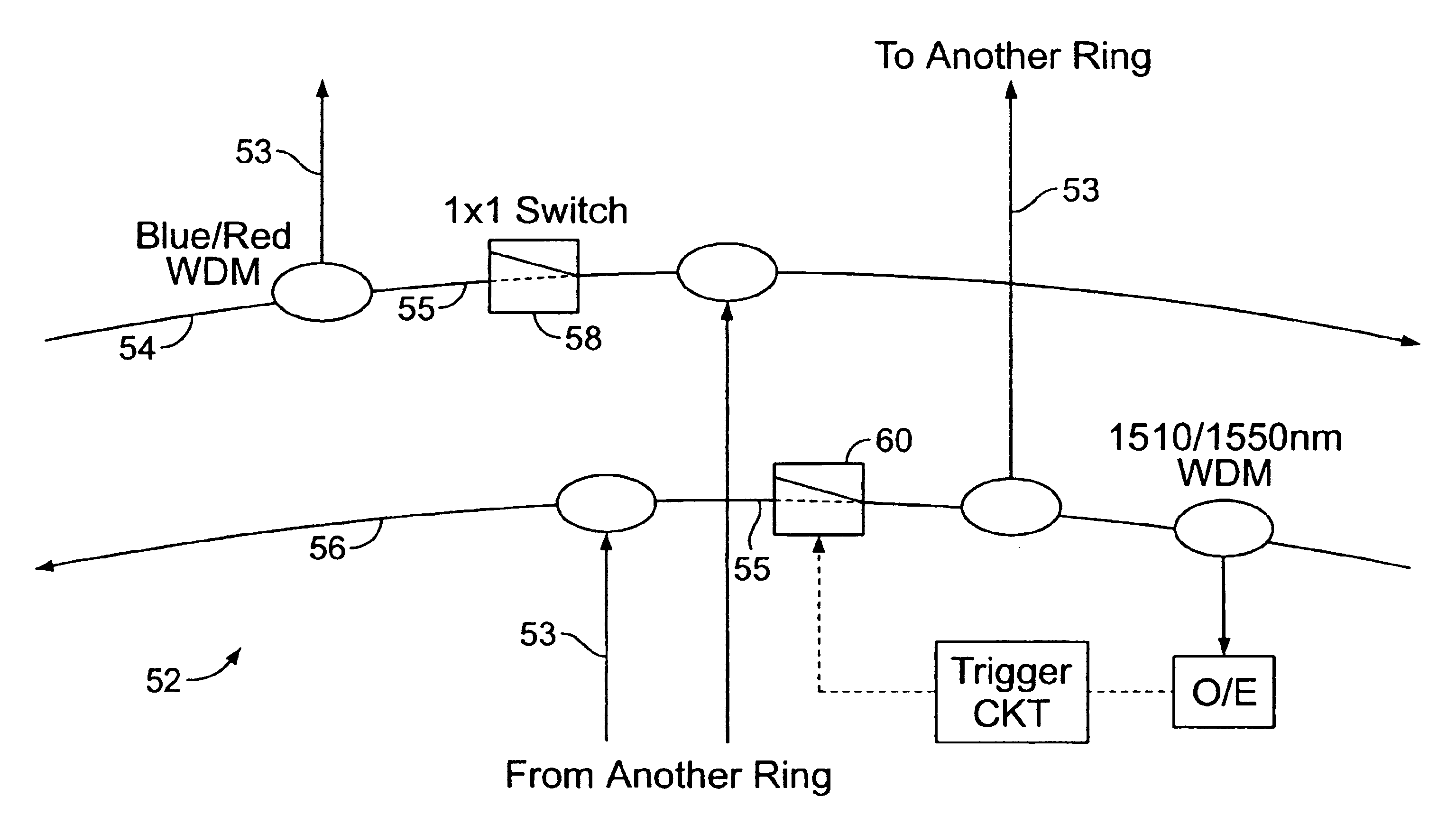
[0045]In one embodiment of the present invention, methods are provided for transmitting optical signal traffic. An all optical network is utilized with at least two rings that are geographically dispersed. Each ring has at least one transmitter and receiver. A sufficiently large enough number of wavelengths is shared in both rings to achieve the sharing without O-E-O conversions between the rings. Alternatively, the available wavelengths are separated into distinct ring bands. The optical signal traffic is shared throughout the entire optical network. Each ring is provided with its own distinct ring band of the optical signal traffic. All of the optical signal traffic is transmittable throughout the optical network. Each receiver is configured to receive only wavelengths in a ring band designated for its associated ring.

[0046]The present invention also provides all optical networks for optical signal traffic. In one embodiment the all optical network has at least first and second ri...


PUM


Abstract

These and other objects of the present invention are achieved in a method of transmitting optical signal traffic. An all optical network is provided with at least two rings that are geographically dispersed. Each ring includes at least one transmitter and at least one receiver. The available wavelengths are separated into distinct ring bands. The optical signal traffic is shared throughout the entire optical network. Each ring is provided with its own distinct ring band of the optical signal traffic. All of the optical signal traffic is transmittable throughout the optical network. Each receiver is configured to receive only wavelengths in a ring band designated for its associated ring.

Description

CROSS-REFERENCE TO RELATED APPLICATIONS[0001]This application claims the priority of U.S. Application No. 60 / 309,220, filed Jul. 31, 2001.BACKGROUND OF THE INVENTION[0002]1. Field of the Invention[0003]The present invention relates generally to all optical networks, and more particularly to an all optical network that has a break point in a hub of a ring that becomes closed when a new break point is created in the network.[0004]2. Description of the Related Art[0005]In today's long-haul dense-wavelength-division-multiplexed (DWDM) optical networks, multiple regenerators have been replaced by optical amplifiers. However, when interconnecting two or more metro ring networks, or when interconnecting a metro ring with long-haul systems, telecom operators are still relying on regenerators and O-E-O wavelength-converters. Wavelength-converters are needed because conventional DWDM systems do not possess enough wavelengths to cover a wide service area such as multiple interconnected rings, ...

Claims


Application Information

Patent Timeline
IPC IPC(8): H04B10/155H04B10/152H04J14/02
CPCH04B10/503H04J14/0228H04B10/564H04J14/0204H04J14/0205H04J14/0206H04J14/0212H04J14/0213H04J14/0227H04J14/0283H04J14/0284H04J14/0286H04J14/0294H04B10/506H04J14/021H04J14/022
Inventor WAY, WINSTON
Owner SNELL HLDG LLC
Learn More