Agricultural harvesting machines and front attachments therefor

a harvesting machine and a technology for tractors, applied in the field of agricultural machinery, can solve the problems of hammering the crop flow, material passing under it, material being lost, etc., and achieves the effects of smooth feeding, improved efficiency and reliability, and improved input speed

Inactive Publication Date: 2005-05-24
BLUE LEAF I P INC +1
View PDF5 Cites 22 Cited by
  • Summary
  • Abstract
  • Description
  • Claims
  • Application Information

AI Technical Summary

Benefits of technology

[0037]Preferably, the speed of the first gathering element varies, within particular limits, in relation to the forward speed of the harvesting machine. For instance, on a pick-up attachment comprising as a first gathering element a rotatable pick-up reel carrying pick-up tines for lifting up or gathering cut grass, hay or straw from the field and as a second gathering element a transverse auger, a minimum speed of the pick-up reel should always be maintained, even at standstill, to enable the reel to pick up crop that has been thrown in front of the machine after reversing the feedrolls. This operation may be needed to clear the machine after detecting a foreign, e.g. metal object or plugging of the feedrolls. It may still be advantageous for the driver to be able to adjust the speed of the first gathering element independently of the instantaneous forward speed of the machine, e.g. when picking up short grass. Then the travelling speed may be high to obtain a high harvesting capacity, while the speed of the first gathering element is preferably relatively low to have a better “raking” effect on the crop on the field. This is because short grass does not behave as an interwoven “carpet” which is pulled into the machine. On row-independent headers, comprising as a first gathering element a plurality of row units provided with forward knives (front rotors) and chain conveyors, and comprising as a second gathering element a transverse auger, the speed of the front rotors should be kept nominal within a tolerance range of + / −25%, because too high a circumferential speed makes maize cobs break off the stalks before the crop reaches the second gathering element. Part of these loose cobs are lost in the field. Maize fields with a lot of grass or weed between the maize plants require a higher than nominal speed (+15%) to ensure that the grass or weeds are properly cut. Under such circumstances an adaptive speed control for the first gathering element may be advantageous, by which the rate of operation of the first gathering element may be varied or adjusted to reflect current or past operation. Where a row-independent header is used to harvest “whole crop” (stems and ears of the grain), the row-independent header comprising as a first gathering element a forward set of rotative cutting and conveying devices, and as a second gathering element a transverse auger or a rearward set of rotative conveying devices, a higher than nominal speed (+25%) is equally required and the adaptive speed control can be used to ensure a proper crop cut.
[0042]Although there has been constant improvement, change and evolution of agricultural harvesting machines, the present concepts are believed to represent substantial and novel improvements that depart from prior practices, resulting in the provision of more efficient and reliable devices of this nature. The used power is spread over all feeder means, whereby no element is pushing or pulling more than another, which results in a smoother feeding, allowing higher input speeds on the harvesting machine and higher handling capacity.

Problems solved by technology

With a forage harvester, when crop material is fed to the feedrolls at a too high speed (speed of the second gathering element higher than the speed of the feedrolls), a plug of material is formed in front of the feedrolls, which hampers the crop flow and causes material to be unevenly cut.
Also when picking up e.g. hay, grass or straw, problems can be caused due to the speed of the second gathering element compared to the speed of the feedrolls: if the speed of the second gathering element is too low, material will pass below it and will be lost; if the speed of the second gathering element is too high, hay will be pushed forward.

Method used


Image

  • Agricultural harvesting machines and front attachments therefor
  • Agricultural harvesting machines and front attachments therefor
  • Agricultural harvesting machines and front attachments therefor

Examples


Embodiment Construction

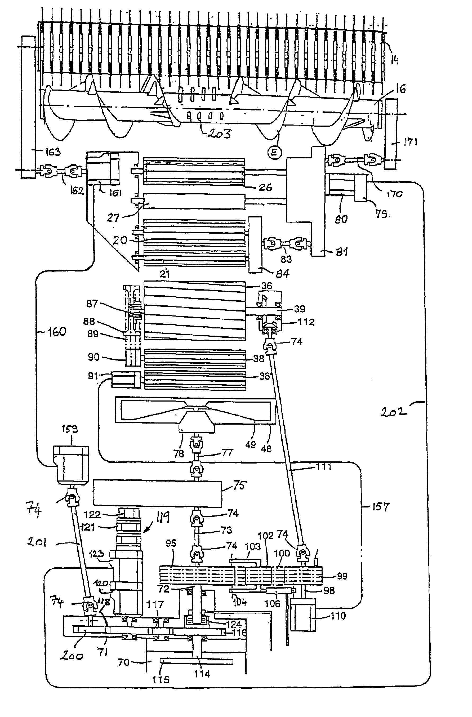
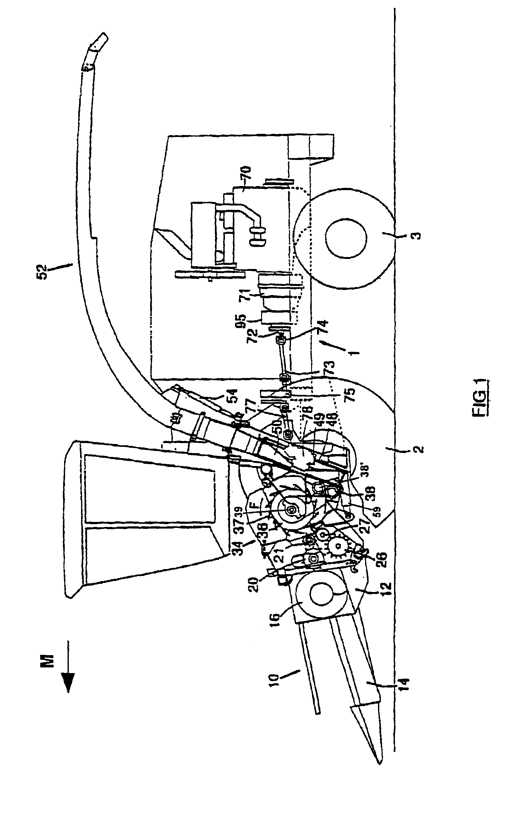
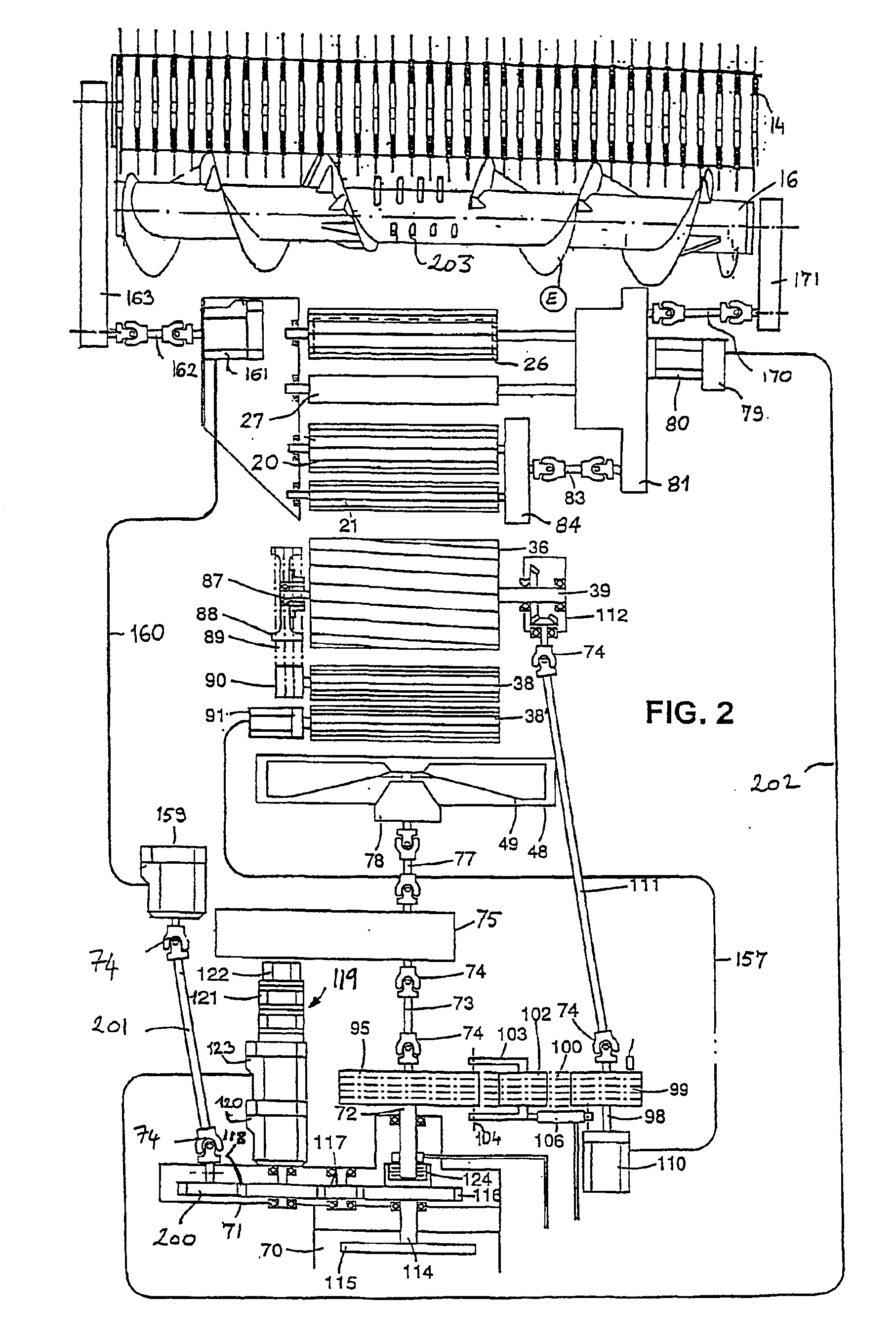
[0049]The present invention will be described with reference to an embodiment of a forage harvester and to certain drawings but the invention is not limited thereto but only by the claims. The drawings are schematic. The terms “front”, “rear”, “forward”, “rearward”, “right” and “left” used throughout the specification are determined with respect to the normal direction of movement of the machine in harvesting operation, as indicated by arrow M on FIG. 1, and are not to be construed as limiting terms.

[0050]With reference to the drawings and more particularly to FIG. 1, there is shown a forage harvester having a main frame 1 on which are mounted ground engaging traction wheels 2 and steering wheels 3. The forage harvester is shown equipped with a crop collecting apparatus / header, in the form of a row crop header attachment 10, suitable for the harvesting of maize, but which can be replaced with a conventional windrow pickup device or a conventional cutter bar attachment, depending on ...


PUM


Abstract

An agricultural harvesting machine is includes a first gathering element (14) adapted to be driven by a first drive mechanism (161) so as to gather crop and to feed the crop in a direction substantially opposite to a direction of motion of the harvesting machine. A second gathering element (16) is adapted to receive the crop from the first gathering element (14) and is further adapted to be driven so as to transfer the crop in a direction substantially transverse to the direction of motion. Intake elements (20, 21, 26, 27) are adapted to receive the crop from the second gathering element (16). The second gathering element (16) and intake elements (20, 21, 26, 27) are adapted to be driven at related rates. The first gathering element (14) is driveable at a rate independent from a driven rate of the second gathering element (16) and the intake elements (20, 21, 26, 27).

Description

TECHNICAL FIELD OF THE INVENTION[0001]The present invention relates to agricultural machinery and in particular to agricultural harvesting machines, front / header attachments therefor and to arrangements for operating the same.BACKGROUND OF THE INVENTION[0002]Some pieces of agricultural equipment known in the art as forage harvesters and combine harvesters are used to collect and process crop material from a field. Generally, such agricultural harvesting machines are equipped with crop material cutting and / or collecting devices, such as maize, corn or grain cutting headers or pick-up units for picking up e.g. hay, grass or straw off the ground. In addition to such initial gathering operations, the machines are also provided with second-stage gathering means for transferring crop material and include intake elements for taking in harvested / gathered crop material and feeding it to further crop processing means of the harvesting machine.[0003]In a forage harvester, for example, the inta...

Claims


Application Information

Patent Timeline
Patent Type & Authority Patents(United States)
IPC IPC(8): A01D41/00A01D41/14A01F29/14A01F29/00
CPCA01F29/14A01D41/142
Inventor AMEYE, DANNY ROGER
Owner BLUE LEAF I P INC
Why Eureka
Try Eureka