
Liquid propellant rocket motor

a rocket motor and liquid propellant technology, applied in the field of liquid propellant rocket motors, can solve the problems of affecting the operation of the rocket engine, so as to prevent damage or disassembly

Inactive Publication Date: 2005-05-24
MCELHERAN TERRY +1
View PDF3 Cites 36 Cited by
  • Summary
  • Abstract
  • Description
  • Claims
  • Application Information

AI Technical Summary

Benefits of technology

[0012]In one aspect of the invention, an inherently safe rocket motor may be constructed. The motor is inherently safe in that the conductivity of the outer shell is indicative of the presence of liquid fuel. A drop in the conductivity is indicative of a loss of cooling and the engine can be shut down to prevent damage or disassembly.

Problems solved by technology

In such motors, liquid fuel is typically combusted in the presence of an oxidizer.
As will be appreciated by those familiar with rocket motor architecture, the inner chamber of a rocket motor is subjected to high temperatures, relatively high pressure, and potentially, an abundance of oxygen, a combination which leads to erosion or consumption of the inside surfaces and weakening of the walls of the motor.
Even with well designed motors, these conditions set a maximum operating life of the motor, often measured in seconds, and, in a poorly designed motor, these conditions often lead to catastrophic failure.
Techniques have been developed to protect the motor from such degradation or self-destruction, but there are limitations or problems associated with these solutions.
While ablative liners are relatively inexpensive, they have a fairly short operating life and are consumed during use.
Regeneratively cooled motors are relatively complex and expensive.
If fuel and oxidizer collect in the chamber before ignition, the engine may experience a hard start, and possibly a resultant disassembly.
Obviously, this technique, the pyrotechnic ignitor, is impractical for applications where a motor will experience intermittent use, such as a thrustor for an orbiting craft or a steering thrustor.

Method used


Image

  • Liquid propellant rocket motor
  • Liquid propellant rocket motor
  • Liquid propellant rocket motor

Examples


Embodiment Construction

[0019]Before explaining the present invention in detail, it is important to understand that the invention is not limited in its application to the details of the construction illustrated and the steps described herein. The invention is capable of other embodiments and of being practiced or carried out in a variety of ways. It is to be understood that the phraseology and terminology employed herein is for the purpose of description and not of limitation.

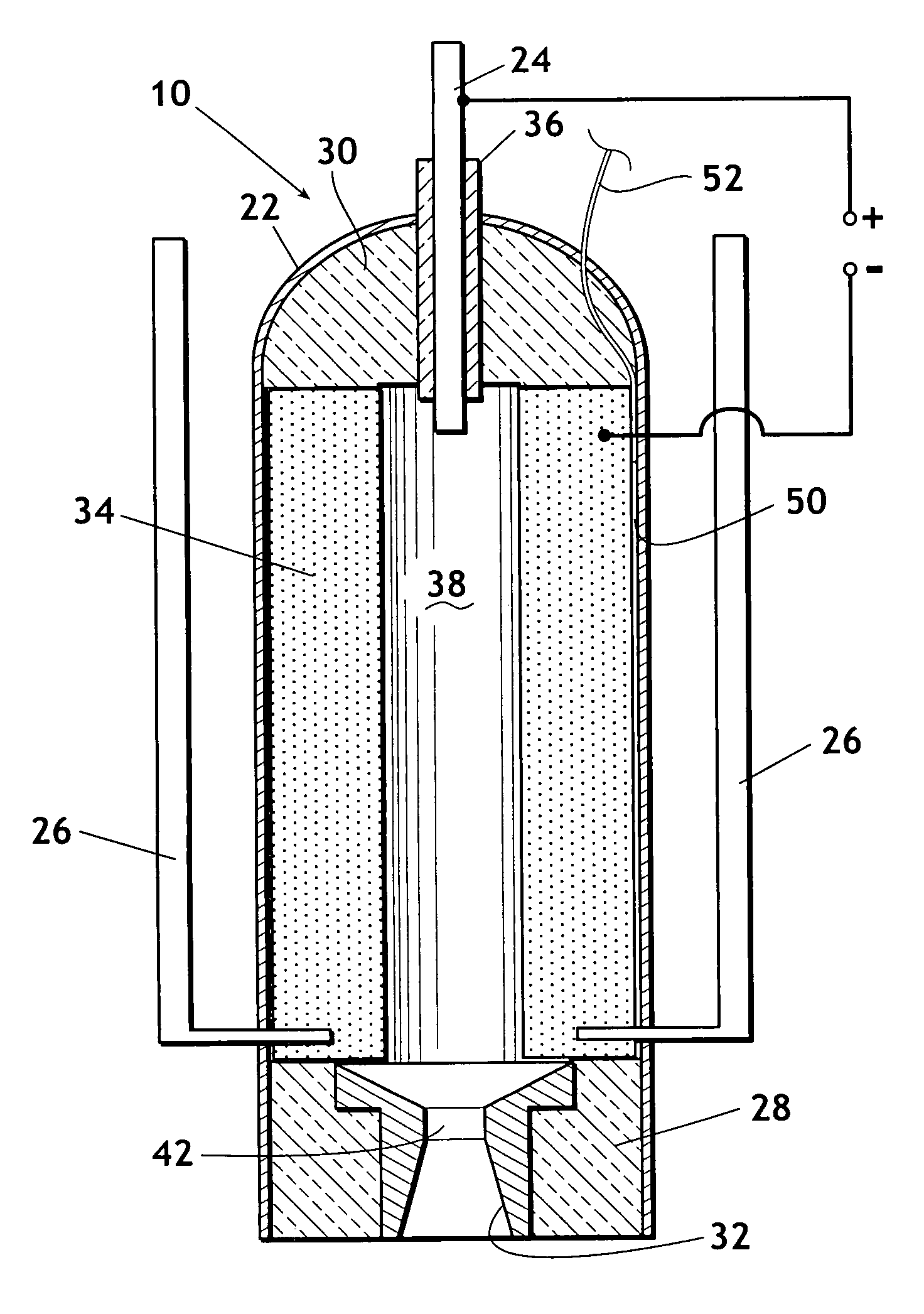
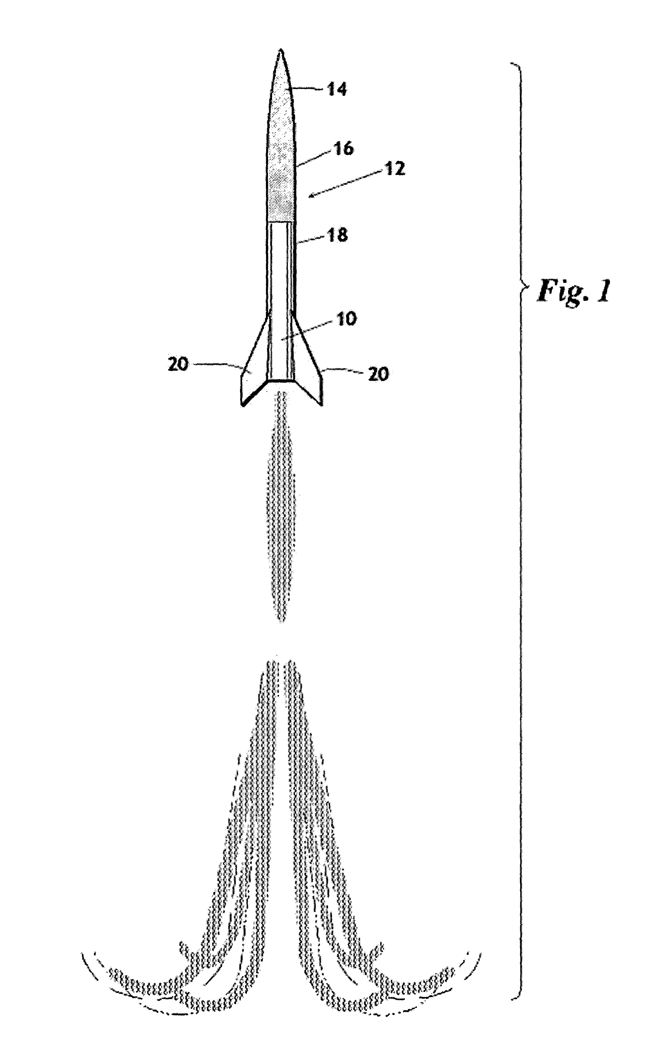
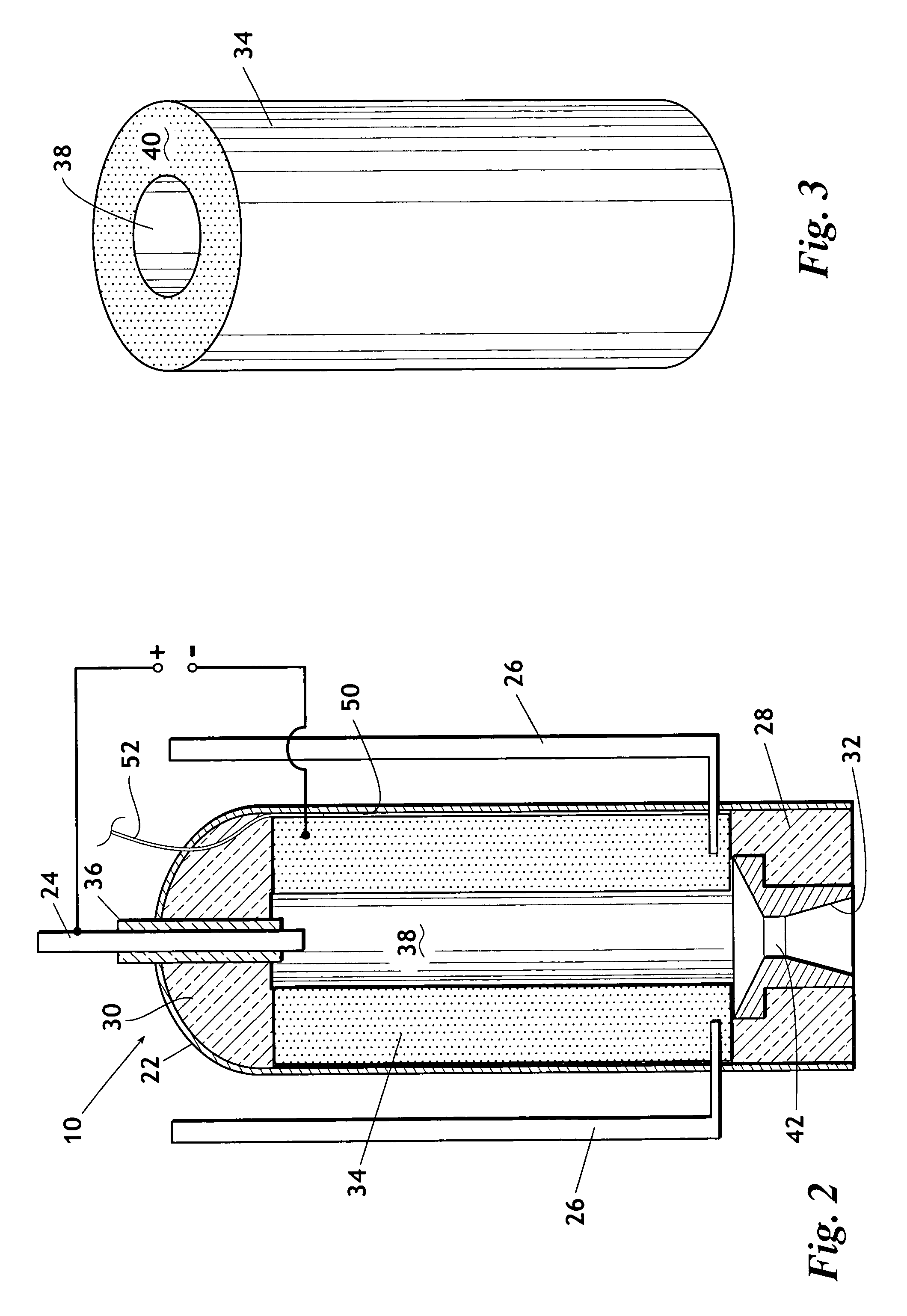
[0020]Referring now to the drawings, wherein like reference numerals indicate the same parts throughout the several views, the inventive rocket motor 10 is shown in its general environment in FIG. 1. In a typical application, rocket motor 10 provides thrust to propel rocket 12 towards apogee, or its final destination. Rocket 12 includes: nose cone 14; payload section 16; fuel tanks 18; and engine 10. Fins 20 act on passing air to maintain rocket 12 in relatively straight flight.

[0021]It should be noted that rocket motor 10 is also wel...


PUM

PropertyMeasurementUnit
Pressureaaaaaaaaaa
Electrical conductivityaaaaaaaaaa
Volumeaaaaaaaaaa

Abstract

The present invention provides a transpiration cooled rocket motor which operates at low combustion pressures, inherently provides stabilized combustion, and operates over a desired range of L-star. In a preferred embodiment the inventive transpiration cooled rocket motor includes: a housing; a porous injector sleeve; a propellant injector; and a nozzle. Preferably the injector sleeve lines the inside walls of the housing such that the inside volume of the sleeve forms the chamber for the motor. Liquid fuel passes inwardly through the pores of the injector sleeve and is injected from the sleeve into the chamber, thus cooling the walls of the rocket motor.

Description

BACKGROUND OF THE INVENTION[0001]1. Field of the Invention[0002]The present invention relates to a liquid propellant rocket motor. More particularly, but not by way of limitation, the present invention relates to a rocket motor which is capable of very long run times without degradation or self destruction.[0003]2. Background of the Invention[0004]Generally speaking, liquid propellant rocket motors are well known in the art but are subject to constant evolution and improvement. In such motors, liquid fuel is typically combusted in the presence of an oxidizer. Hot exhaust gases are discharged through a nozzle to generate thrust. While there are any number of fuel and oxidizer combinations, kerosene and alcohol are common fuels and oxygen, stored in compressed liquid form, and nitrous oxide are common oxidizers.[0005]As will be appreciated by those familiar with rocket motor architecture, the inner chamber of a rocket motor is subjected to high temperatures, relatively high pressure, ...

Claims


Application Information

Patent Timeline
IPC IPC(8): F02K9/64F02K9/42F02K9/00F02K9/95
CPCF02K9/425F02K9/64F02K9/95F05D2300/21F05D2260/232F05D2260/203
Inventor MCELHERAN, TERRYCOLBURN, WILLIAM
Owner MCELHERAN TERRY
Learn More