Ignition and injection control system for internal combustion engine

a control system and injection technology, applied in the direction of braking system, process and machine control, instruments, etc., can solve the problems of increasing the required energy amount for introducing a required spark at each discharge, increasing the manufacturing cost, and enlarging the circuit scale. , to achieve the effect of improving fuel consumption

Inactive Publication Date: 2005-05-24
DENSO CORP
View PDF26 Cites 21 Cited by
  • Summary
  • Abstract
  • Description
  • Claims
  • Application Information

AI Technical Summary

Benefits of technology

[0017]A first object of the present invention is to supply discharge energy effectively during a multiple discharges operation, and to reduce the size of an ignition device.
[0019]Thus, the energy amount consumed at each discharge of multiple discharges operation is suppressed toward the minimum requirement, and the consumption of energy accumulated in the ignition device is appropriately controlled. As a result, discharge energy is efficiently consumed at the multiple discharges, thereby compacting the ignition device. Further, the number of multiple discharges is not restricted.
[0020]A second object of the present invention is to simplify a circuit arrangement for an engine control to reduce the manufacturing cost.
[0022]Thus, the wiring pattern is simplified between the ignition operating circuit and the injection operating circuit, and the ignition operating circuit and the injection operating circuit easily share the function device commonly used for both circuits. Therefore, circuit arrangement of ignition and injection systems and assembling procedure are simplified, thereby reducing the manufacturing cost.
[0023]A third object of the present invention is to effectively use a remaining energy between the ignition operating circuit and the injection operating circuit.
[0025]Thus, the remaining magnetic energy is effectively consumed, thereby improving fuel consumption.

Problems solved by technology

However, the required energy amount for introducing a required spark at each discharge gradually increases.
Thus, the multiple discharges operation cannot be executed.
Thus, even when there is a function device commonly used for both circuits, the function device cannot be shared from a circuit arrangement standpoint, thereby enlarging the circuit scale and increasing the manufacturing cost.
Thus, a wide wiring space is needed, and the arrangement of the signal lines becomes complicated, thereby increasing the manufacturing cost.
According to the conventional engine control system, a combustion sensor is provided in each cylinder, thereby increasing the manufacturing cost.
However, the energy is emitted as heat and is not effectively used.

Method used


Image

  • Ignition and injection control system for internal combustion engine
  • Ignition and injection control system for internal combustion engine
  • Ignition and injection control system for internal combustion engine

Examples


first embodiment

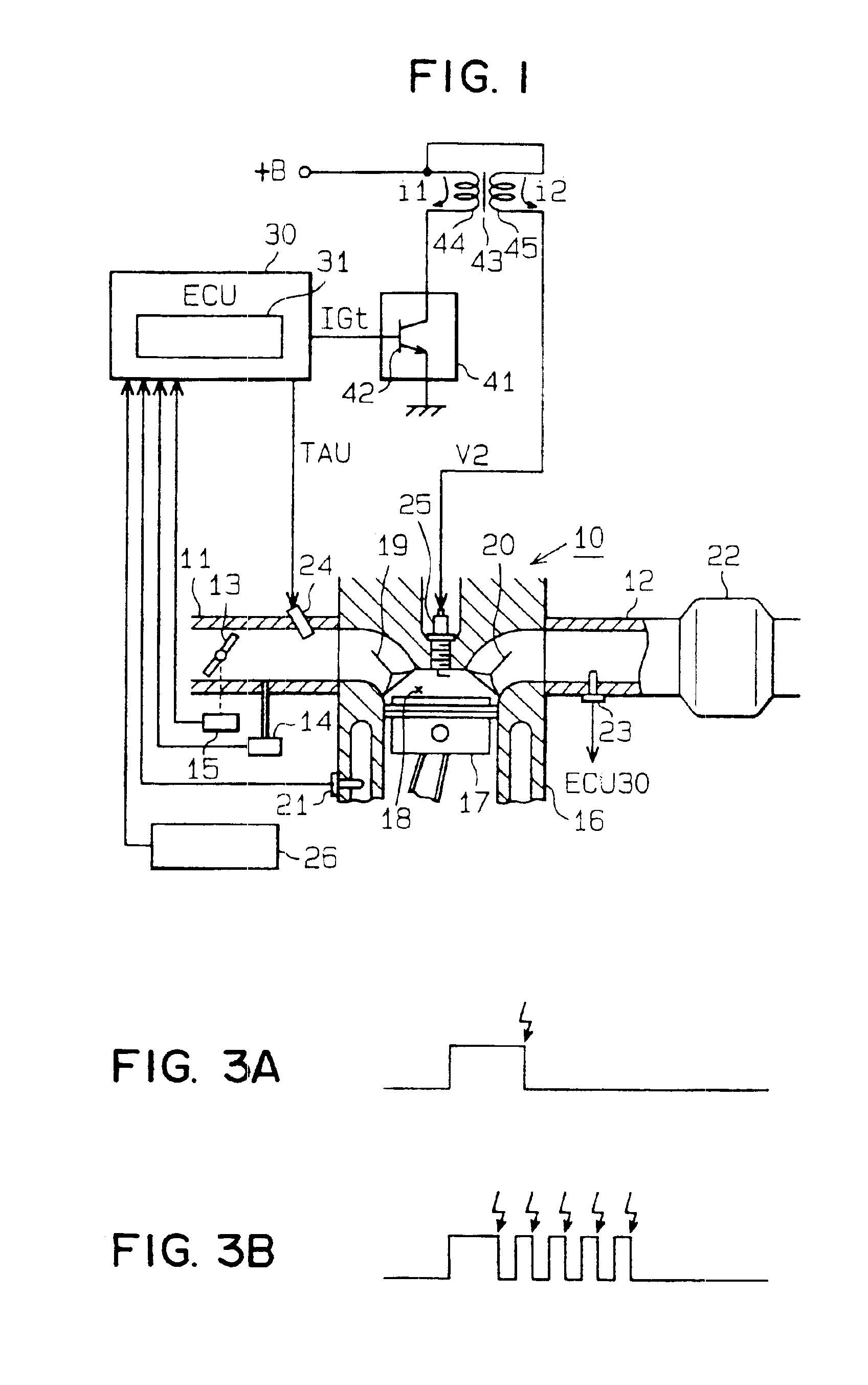
[0053]In an internal combustion engine, for example, a spark ignition 4-cycle 4-cylinder engine, the ignition timing thereof is controlled by an ECU. In this engine, a plurality of electric discharges are carried out during one combustion cycle. That is, multiple discharge is executed.

[0054]FIG. 1 is a schematic view showing an engine control system of the present invention. As shown in FIG. 1, an intake port of an engine 10 connects with an intake pipe 11, and an exhaust port of the engine 10 connects with an exhaust pipe 12. In the intake pipe 11, a throttle valve 13 and an intake air pressure sensor 14 are provided. The throttle valve 13 interlocks with an accelerate pedal (not illustrated), and the intake air pressure sensor 14 detects an air pressure inside the intake air pipe 11. A throttle sensor 15 detects an opening degree of the throttle valve 13. The throttle sensor 15 also detects a full close position (idle position) of the throttle valve 13.

[0055]A piston 17 is provide...

second embodiment

[0094]In the first embodiment, the multiple discharges operation is applied at the cold start of a port injection type engine. According to the present second embodiment, the multiple discharges operation is applied to a cylinder inside injection type engine. The multiple discharges operation is executed for igniting stratified mixed gas with certainty at stratified combustion of the engine to prevent an accidental fire.

[0095]In the second embodiment, a high-pressure swirl injector is provided under the intake port of the engine 10 in FIG. 1. High pressure fuel is injected from this injector toward the top of the piston inside the combustion chamber. The piston includes a concave portion at the top surface thereof. Fuel injection flow from the injector is led along the inner periphery surface of the concave portion toward the spark point (tip end) of the ignition plug 25.

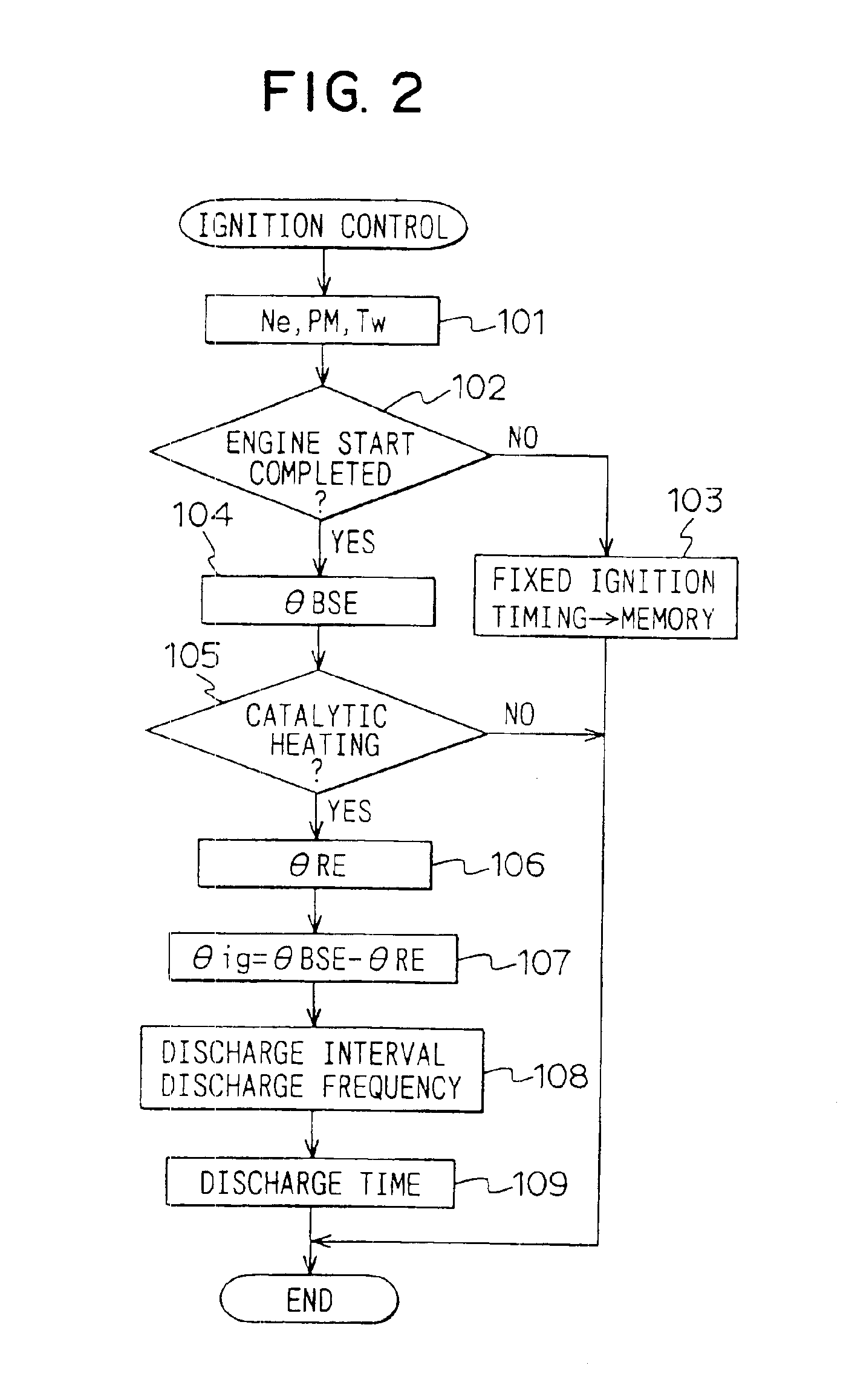
[0096]FIG. 11 shows a flow chart of the ignition control. This execution corresponds to an ignition control means...

third embodiment

[0113]In the third embodiment, as shown in FIG. 15, an ignition operating circuit 61 and an injection operating circuit 63 are arranged on a single substrate. The ignition operating circuit 61 controls an ignition system, and the injection operating circuit 63 controls a fuel injection valve 62. The ignition operating circuit 61 and the injection operating circuit 63 share a battery stabilizing circuit 64. The battery stabilizing circuit 64 suppresses voltage fluctuation and noises in a battery 65. The battery stabilizing circuit 64 includes a LC low pass filter in which a coil 66 and a condenser 67 are connected in series between the positive terminal and ground terminal of the battery 65. A connection point between the coil 66 and the condenser 67 defines an output terminal 68 of the battery stabilizing circuit 64. Vehicle battery voltage VB is supplied to the ignition operating circuit 61 and the injection operating circuit 63 through the output terminal 68 and battery lines 69a,...


PUM


Abstract

During a multiple discharges operation, a micro computer changes a discharge period of each discharge in accordance with a pressure transition in a combustion chamber of an internal combustion engine. Thus, the energy amount consumed at each discharge of multiple discharges operation is suppressed toward the minimum requirement, and the consumption of energy accumulated in the ignition device is appropriately controlled. As a result, discharge energy is efficiently consumed at the multiple discharges, thereby compacting the ignition device. Further, the number of multiple discharges is not restricted.

Description

[0001]This application is a Divisional of Ser. No. 09 / 713,228 filed Nov. 16, 2000 now U.S. Pat. No. 6,694,959.CROSS REFERENCE TO RELATED APPLICATION[0002]This application is based on and incorporates herein by reference Japanese Patent Application Nos. Hei. 11-329906 filed on Nov. 19, 1999, and Hei. 11-337821 filed on Nov. 29, 1999.BACKGROUND OF THE INVENTION[0003]1. Field of the Invention[0004]The present invention relates to an ignition and injection control system for an internal combustion engine suitable for use in a vehicle.[0005]2. Description of Related Art[0006]Conventionally, an ignition control system executes a multiple electric discharges operation. In the multiple electric discharges operation, a plurality of discharges are carried out during one engine combustion cycle. For executing the multiple discharges, for example, an ECU outputs an ignition signal IGt to energize and de-energize the primary coil of an ignition coil repeatedly. Thereby, high voltage is introduce...

Claims


Application Information

Patent Timeline
Patent Type & Authority Patents(United States)
IPC IPC(8): F02P15/00F02P3/02F02P15/08F02P3/05
CPCF02P3/053F02P15/08F02P15/006
Inventor MIWA, TETSUYACHIBA, TOMONARI
Owner DENSO CORP
Why Eureka
Try Eureka