System and method for installation and use of devices in microboreholes

Inactive Publication Date: 2005-05-24
SCHLUMBERGER TECH CORP
View PDF12 Cites 48 Cited by
  • Summary
  • Abstract
  • Description
  • Claims
  • Application Information

AI Technical Summary

Benefits of technology

[0014]As used herein the term microlaterals and microboreholes means any holes bored from a main borehole having a diameter substantially less than that of the main borehole and a length longe

Problems solved by technology

The holes in the casing created by shaped charges are not smoothly shaped, but are ragged or rough; this makes them difficult to seal, should this be required.
Due in large part to the afores

Method used


Image

  • System and method for installation and use of devices in microboreholes
  • System and method for installation and use of devices in microboreholes
  • System and method for installation and use of devices in microboreholes

Examples


Embodiment Construction

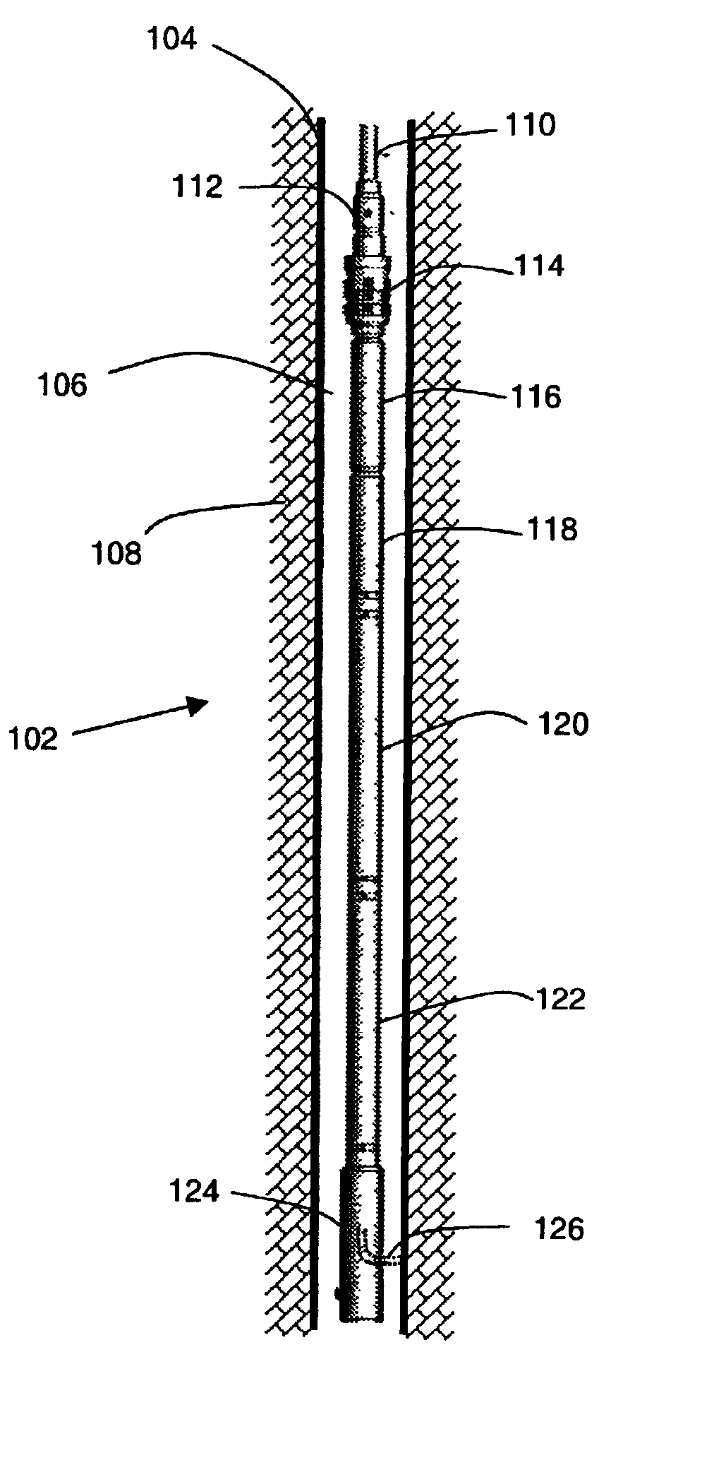
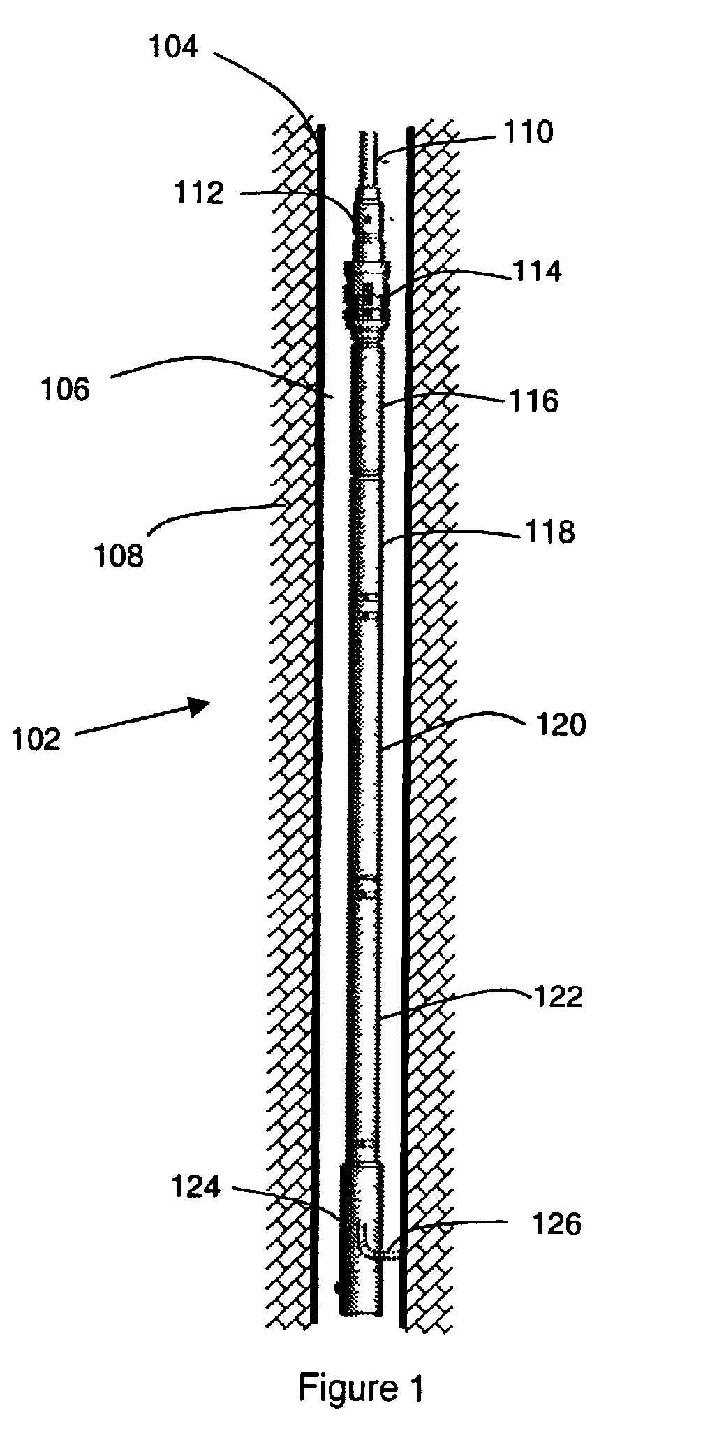
[0019]According to the invention, creating a relatively smooth hole through the casing and formation, with a known size, allows emplacement of sensors or other devices, followed by sealing of the hole in the casing to give isolation of the sensor from the contents of the wellbore. This can be done, for example, by Schlumberger's Cased Hole Dynamics Tester, mounted on the MDT platform on wireline. See U.S. Pat. No. 5,692,565, hereby incorporated herein by reference. See also, “Wireline-Conveyed Through-Casing Formation Tester Preserves Casing Integrity” by Burgess et al., Society of Petroleum Engineers, SPE 72371.

[0020]With this type of arrangement, the maximum depth of the hole is currently limited to around 150 mm. This depth allows fluid sampling or a valid measurement of formation fluid pressure in a permeable formation from a cased well. However, some types of measurements in a hole of this depth would be compromised by the proximity of the main borehole. For example, formation ...


PUM


Abstract

The present invention provides methods and systems for making measurements associated with a rock formation including a main borehole, a microborehole extending from the main borehole into the rock formation, and one or more sensing devices positioned and arranged to make a measurement at measurement zones being located in the microborehole. A packer can also be installed in the microborehole dimensioned and arranged to hydraulically isolate the measurement zones from conditions present in other parts of the microborehole and/or main borehole. Methods and systems are also provided for taking fluid samples and injecting fluid tracers in a microborehole.

Description

FIELD OF THE INVENTION[0001]The present invention relates to the field of boreholes oilfield services applications. In particular, the invention relates to methods and systems which are used in microboreholes or microlaterals opened from a main wellbore.BACKGROUND OF THE INVENTION[0002]Drilling secondary holes from a main borehole is an established technology, for example in creating sidetracks and multilateral wells for formation evaluation or production enhancement. These multilaterals have diameters comparable to the parent borehole. Because of the stiffness of the assembly used to drill them, they take off from the parent hole at a shallow angle, leaving a large elliptical opening at the junction. If the junction needs to be sealed, this requires a considerable investment in a mechanical junction of some kind, over and above the investment of time and money required to drill the multilateral hole in the first place.[0003]Because of this, a multilateral well is typically drilled ...

Claims


Application Information

Patent Timeline
IPC IPC(8): E21B49/10E21B49/00E21B33/12E21B33/124E21B47/00E21B41/00G01V11/00
CPCE21B33/124E21B41/0042E21B47/00G01V11/00G01V11/005E21B49/10G01V2210/6163E21B41/00
Inventor COOK, JOHN MERVYNCOOPER, IAINJEFFRYES, BENJAMIN PETERCOATES, RICHARD TIMOTHYWANG, WILLIAM LI-TIENHAMMOND, PAULCHRISTIE, PHILIPNICHOLS, DAVIDBOLCHOVER, PAUL
Owner SCHLUMBERGER TECH CORP
Why Eureka
Try Eureka