Pinch-grip hanger

a technology of pinch-grip and hanger, which is applied in the field of pinch-grip hangers, can solve the problems of pinch-grip opening and losing the garment, not being well suited to the use of pinch-grip hangers in the transportation (shipping) of garments, and being highly undesirable, so as to prevent accidental opening of pinch-grip

Inactive Publication Date: 2005-05-24
VISCONTI POLYOAK
View PDF49 Cites 10 Cited by
  • Summary
  • Abstract
  • Description
  • Claims
  • Application Information

AI Technical Summary

Benefits of technology

[0019]Each pinch-grip also preferably includes spacers or “bumpers” on each side thereof which extend outwardly from the back leg towards the front leg. These protectors prevent the accidental opening of the pinch-grip by providing a hanger-to-hanger minimum spacing while still enabling the intentional movement of the pinch-grip into the fully extended open position.
[0020]In a preferred embodiment, the legs include, on the opposed surfaces thereof, vertically offset wall sections which extend in back-to-front overlapping relationship from the inner surface of each of the pinch-grip components and are located below to the pivot area of the pinch-grip. The opposed wall sections cooperate to form a barrier that prevents the garment from being pinched within the pivot area of the pinch-grip. In addition the upper portions of the front legs are angled relative to the lower portions to facilitate full opening when the upper portions of the front and back legs are pressed together. The angle is such that the upper portions of the legs do not become parallel to each other until the bottom ends have been separated as far as possible.

Problems solved by technology

In particular, pinch-hangers are not well suited for use in the transport (shipping) of garments suspended from or attached to the pinch-grips.
Thus, when garments are transported by various vehicles, abrupt starts-and-stops, turning or the like may result in a pinch-grip opening and losing the garment.
Clearly this is highly undesirable as the garment falling completely or partially onto a floor may become ruined or may at least require pressing before it is ready to be displayed for sale.
Likewise, labor costs are incurred in picking up the fallen garments during transport and reinserting them in the pinch-grip.
Attempts to solve these problems have sometimes resulted in creation of other problems.
Some of these do prevent the pinch-grip from opening prematurely, but in some cases, these “bumpers” have shaped in a way that prevents comfortable access of fingers to the pressing surfaces of the upper portion, in particular larger fingers, thereby preventing the pinch-grip components from being intentionally pressed into a fully open position.
Other problems also exist in conventional pinch-hangers.
Also, handlers of the garments, be they employees or customers, typically force the garments as far as possible into the pinch-grip before closing it, thereby compounding the creasing problem.
Moreover, known pinch-hangers are, due to their design, restricted in their ability to accommodate and secure bulky garments having an enlarged waistband area such as denim jeans or pants having a belt provided.
Garment waistbands may also be thin and difficult to effectively grip.
Because of this, various “teeth” configurations are used, all of which leave multiple markings on the garment that are undesirable.
The configuration of these gripper teeth can also interfere with the process of loading the garment into the pinch-grip.
Further, these teeth are typically point-shaped, i.e., angled on two sides and are arranged in multiple rows; i.e., staggered, which results in an unsightly pattern of marks on the garment.
Moreover, it is found that pointed teeth are not always the most effective method for reliably holding a wide variety of fabrics.
Further, the use of staggered teeth results in uneven pressure to the fabric, thereby causing stress on the fabric weave and resulting in puckering damage as well as undesirable indentation markings on the garment.
In addition, conventional biasing mechanisms used to maintain the pinch-glips closed are not entirely satisfactory.
One known problem is that when the hangers are exposed to extreme temperatures (for example, in a shipping container), the plastic materials typically used for the hangers can soften and bend sufficiently to reduce the amount of pressure that the “teeth” can apply to the garment.
Investigation has indicated that this is due, at least in part, to the fact that, in conventional designs, the biasing forces are not effectively directed toward the area of contact between the pinch-grip and the garment.

Method used


Image

  • Pinch-grip hanger
  • Pinch-grip hanger
  • Pinch-grip hanger

Examples


first embodiment

[0037]Referring to FIGS. 1-7, wherein like reference numerals indicate like elements, there is shown a garment hanger in accordance with the present invention. The garment hanger shown can be made from any suitable known material and by any suitable known method. Preferably, the garment hanger is made of injection molded plastic.

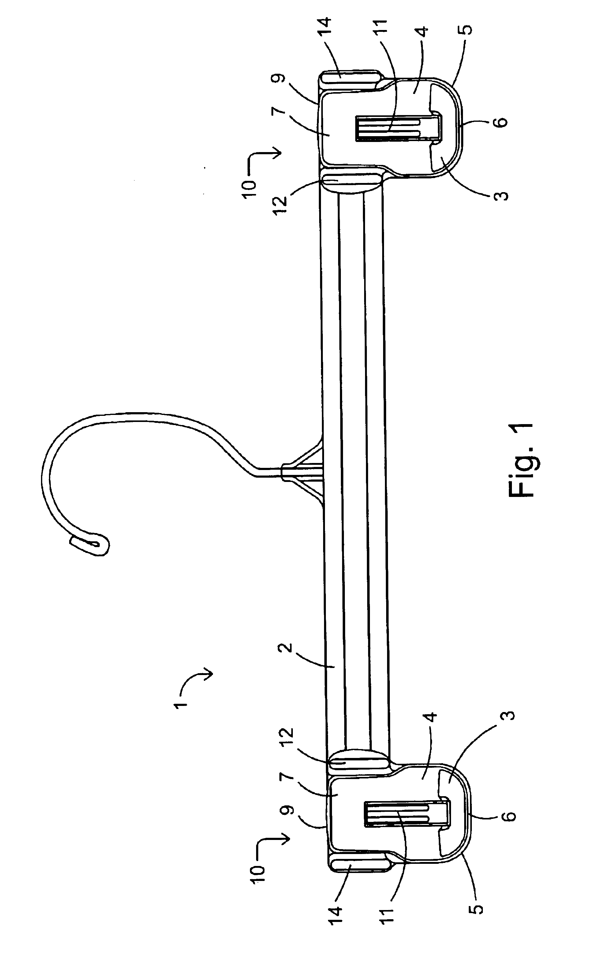
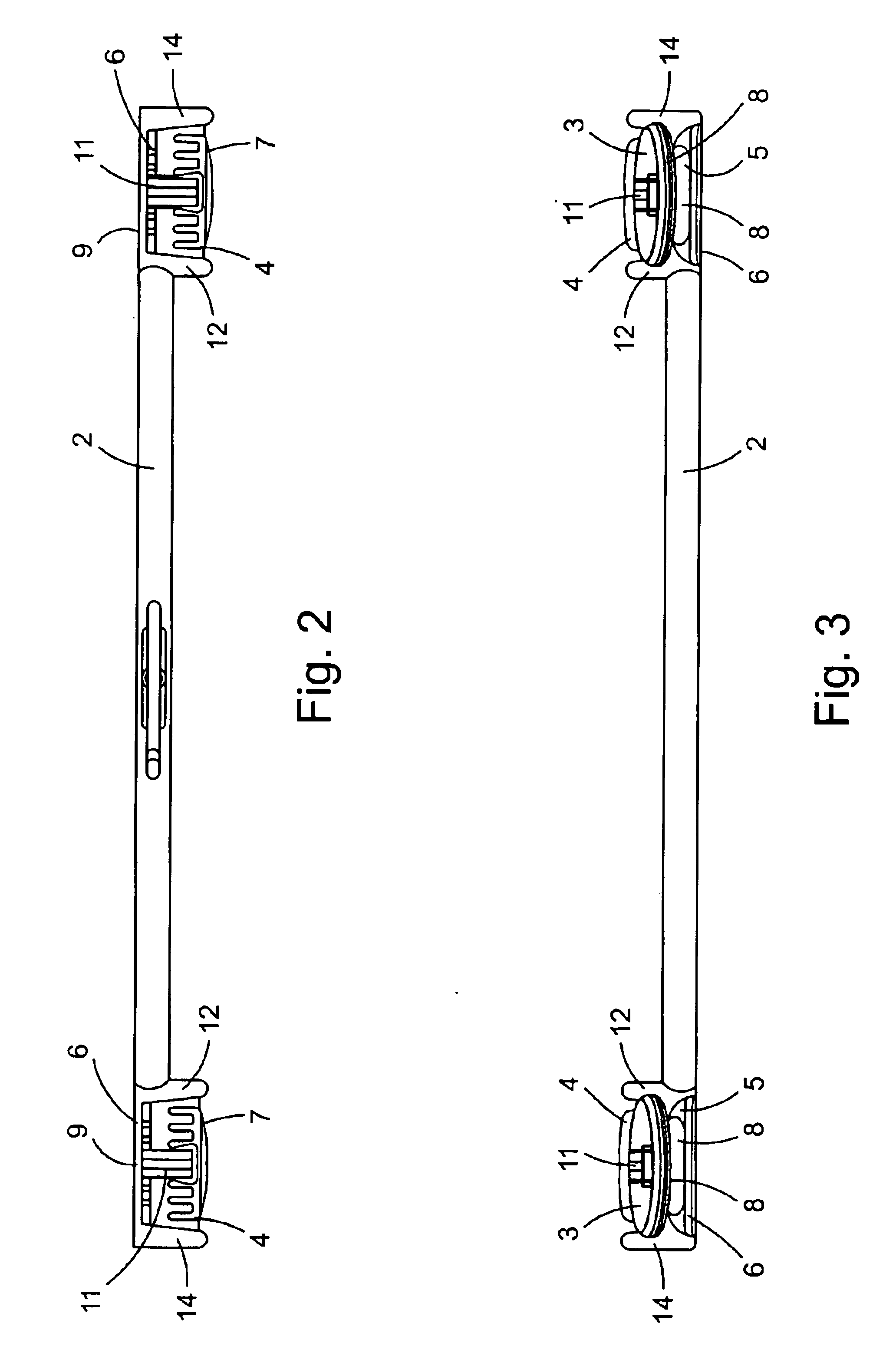
[0038]As shown in FIG. 1, the pinch-hanger 1 includes a pinch-grip 10 on each end of a hanger body 2. Each pinch-grip 10 includes a movable first gripping component or leg 4 and a stationary second gripping component or leg 6 secured to each other about a pivot axis. Each of components 4 and 6 includes respective lower ends 3, and 5 below the pivot axis for receiving a garment therebetween and respective upper ends 7 and 9 above the pivot axis. The upper ends 7 and 9 are preferably sized, in this first embodiment, to be substantially equal in length to their respective lower ends 3 and 5. This “long-lever engineering” allows for easier opening of the pinch-g...

second embodiment

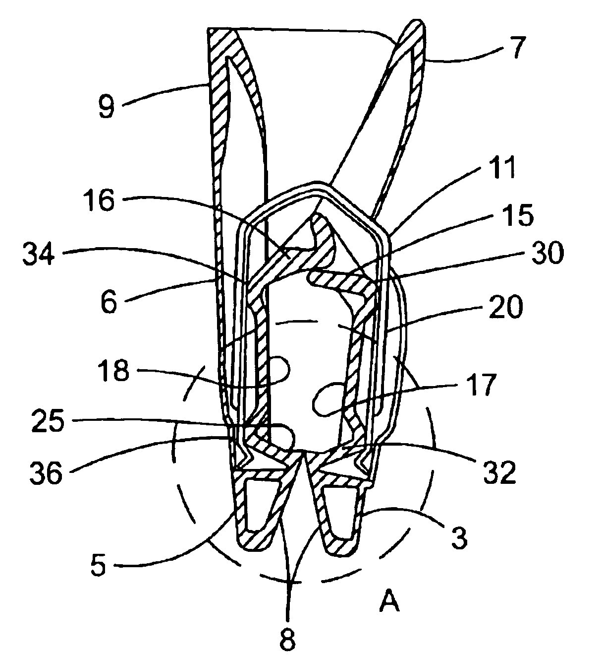
[0055]Referring now to FIGS. 8 through 14, the pinch-hanger is disclosed. In this embodiment, the lower ends 3 and 5 of the pinch-grips legs 4 and 6 are extended, or elongated below the point at which the biasing force is applied by spring 11, to allow the pinch-grips to grab difficult to hang garments with enlarged waistbands or waistbands with a belt fitted thereto. This lengthening of the gripping space 20 permits the gripping teeth 8a to engage the garment below the stitching line of the waistband area. With this, the gripping portion 8 and gripping teeth 8a grab below the thicker waistband and hold the bulky garment very securely.

[0056]Longer springs may be fitted to also provide pressure behind the gripping teeth. This may not be necessary as gripping underneath the step provided by the waistband requires less pressure than is required normally.

[0057]All other components described above with reference to the first embodiment of FIGS. 1-7, and having the same reference numerals...


PUM


Abstract

A pinch-grip hanger includes an elongated body with first and second pinch-grips positioned along the body. Each pinch-grip has a stationary back leg and a front leg movable about a pivot axis, with single gripping portions at the lower ends thereof. An inverted U-shaped spring applies a force near the lower ends of the legs to bias the gripping portions thereof toward each other. Moving the upper ends of the front leg rearwardly separates the gripping portions, thereby opening the pinch-grip. Spacers at opposite sides of the legs extend in the front-to-back direction a sufficient distance so that contact with another hanger on a rack will not move the upper ends of the legs toward each other a sufficient distance to release an item being held by the gripping portions. Opposed overlapping barriers extend from the front and back legs just below the pivot axis. These shield an item held by the hanger from the area near the pivot axis. The gripping portions each have a single gripping tooth, the tips of which are substantially in contact when the pinch grip is closed and an item is not being held by the hanger. The teeth have substantially planar parallel upper surfaces that together define the lower end of the gripping area between the gripping portions. The gripping portions also have outwardly tapering end portion with substantially smooth surfaces extending downward below the teeth.

Description

CROSS REFERENCE TO RELATED APPLICATION[0001]This application is based on and claims benefit of U.S. Provisional Patent Application No. 60 / 281,454 filed Apr. 4, 2001 entitled PINCH HANGER, the disclosure of which is hereby incorporated by reference and to which a claim of priority is hereby made.BACKGROUND OF THE INVENTION[0002]1. Field of the Invention[0003]The present invention relates to garment hangers and, more particularly, to garment hangers that are capable of displaying garments through the use of pinch-grips on each end of the hanger body.[0004]2. Description of the Related Art Various types of pinch-hangers are known. These hangers include an attachment portion for securing the hanger body to a support (typically, a hook that secures the hanger body to a rod), and pinch-grips attached to the hanger body, typically at opposite ends thereof. Each pinch-grip includes a pair of vertically-extending gripping components, a mechanism for pivotally securing the components together...

Claims


Application Information

Patent Timeline
Patent Type & Authority Patents(United States)
IPC IPC(8): A47G25/48A47G25/00
CPCA47G25/483
Inventor LOUW, HENRY
Owner VISCONTI POLYOAK
Why Eureka
Try Eureka