Connector provided with shutter

a technology of connecting rods and shutters, applied in the direction of fixed connections, coupling device connections, instruments, etc., can solve the problems of inability to smoothly move, inconvenient connection, and inability to avoid dust invasion above the surface of the connection

Inactive Publication Date: 2005-05-24
MITSUMI ELECTRIC CO LTD
View PDF9 Cites 33 Cited by
  • Summary
  • Abstract
  • Description
  • Claims
  • Application Information

AI Technical Summary

Benefits of technology

[0008]It is therefore an object of the invention to provide a connector provided with a shutter, which is capable of positively covering a connector fitting section in such a manner that any gap through which internal terminals are exposed to the exterior is eliminated.
[0014]With this configuration, the size of the shutter members are not so limited. Therefore, the pair of shutter members having a sufficient size to cover the opening of the cavity are used. When the shutter members are placed in the first position, the opening is completely concealed without forming any gap through which the internal terminal is exposed to the exterior. Accordingly, dust and other objects are almost completely prevented from intruding into the cavity from the exterior.
[0016]With this configuration, the slope faces serve as the guide portions for the insertion of the mating connector terminal. Therefore, as the mating connector terminal is attached in registry with the guide portions, the pair of shutter members are opened in the second direction, respectively. As a result, the guiding of the mating connector terminal and the opening of the shutter members are effected at the same time, and therefore the mating connector terminal can be easily fitted into the cavity.
[0018]With this configuration, the shutter members can be easily formed, for example, by an injection molding technique. In addition, it is possible to secure the insulation with respect to the mating connector terminal which is abutted against the shutter members.

Problems solved by technology

When such a connector under the non use condition is exposed to the ambient air for a long time, dust deposits on internal terminals (contacts) provided within the connector fitting section, or the internal terminals can corrode, which leads to a possibility that incomplete contact is encountered when the mating connector terminal is inserted into the connector fitting section.
Therefore, when the shutter member moves within the connector fitting section, a side edge of the shutter member sometimes contacts the internal terminals within the connector fitting section, and therefore fails to smoothly move.
Therefore, the above problems in connection with the dust invasion cannot be avoided.

Method used


Image

  • Connector provided with shutter
  • Connector provided with shutter
  • Connector provided with shutter

Examples


Embodiment Construction

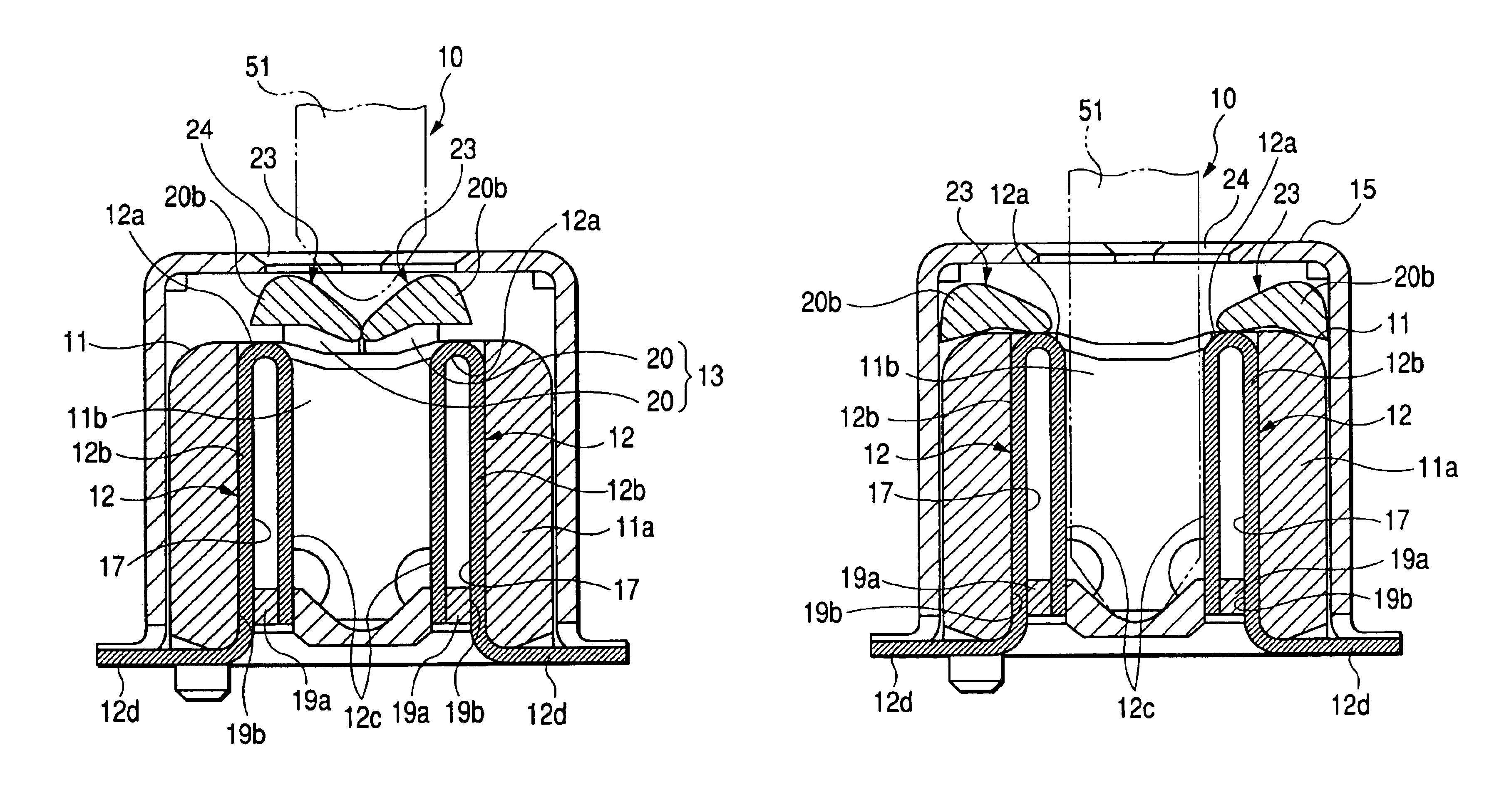
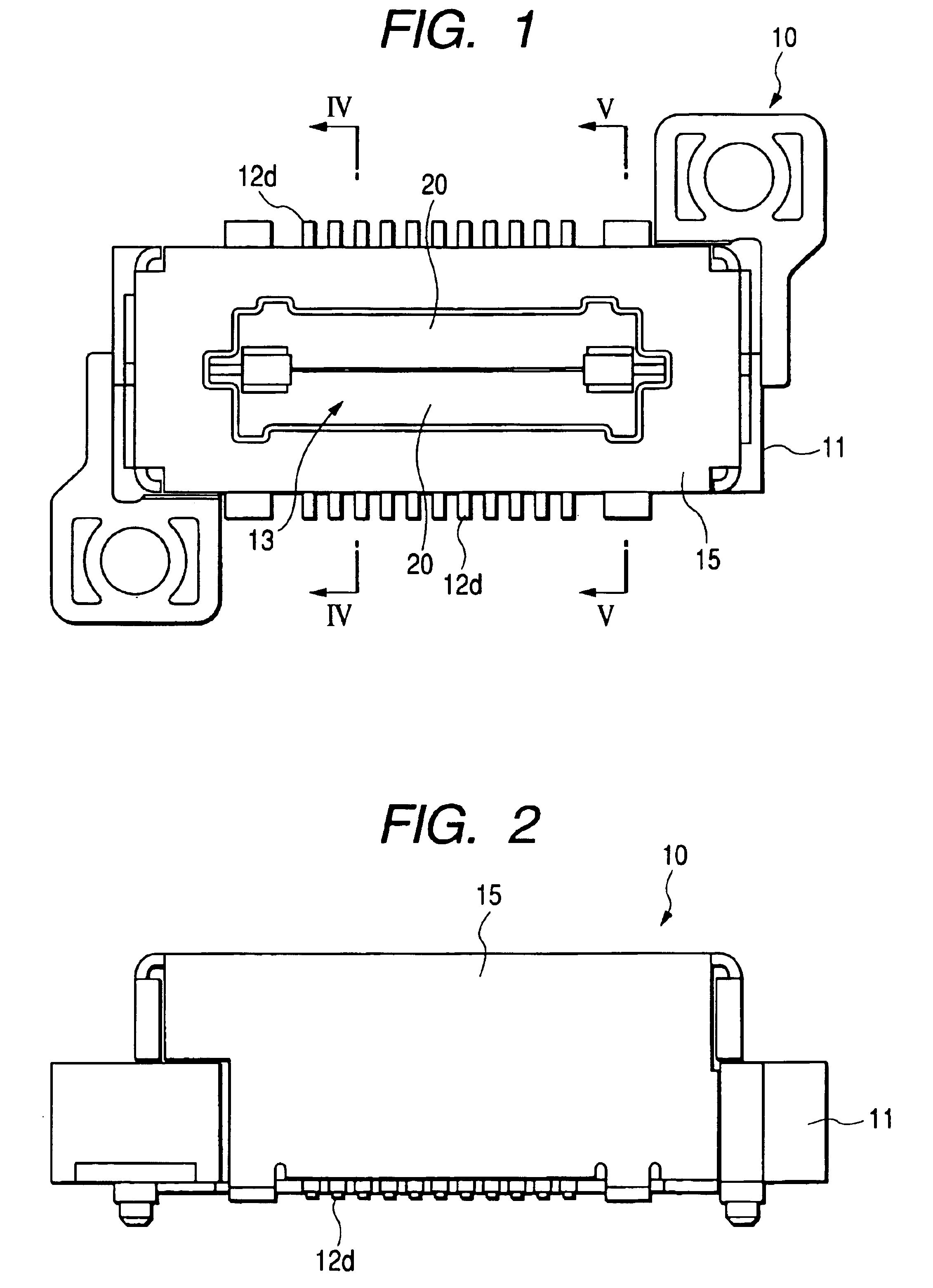
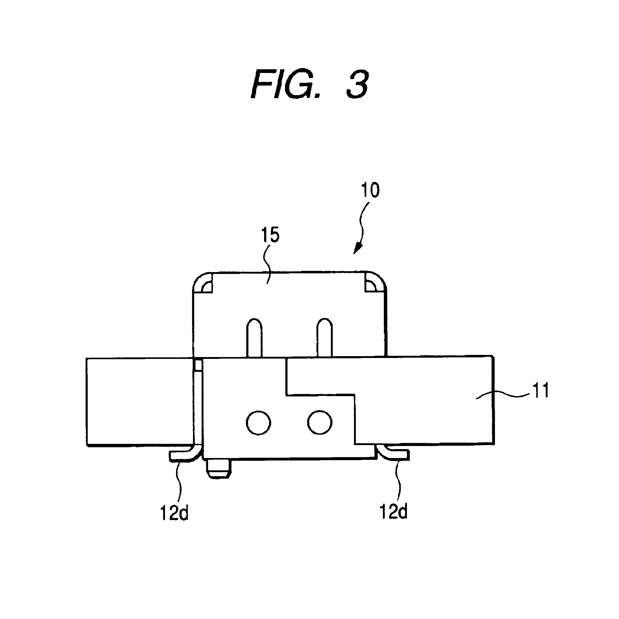
[0031]Preferred embodiments of the present invention will be described below in detail with reference to the accompanying drawings. FIGS. 1 to 6 show a connector 10 according to a first embodiment of the invention. The connector 10 comprises a housing 11, contacts 12, a shutter 13, springs 14, and a shield casing 15.

[0032]The housing 11 is made of a resin material such as nylon. As shown in FIGS. 1 to 5, this housing 11 includes a rectangular box-shaped housing body 11a. The housing body 11a is formed with an opening formed in an upper face thereof for receiving a mating connector terminal therethrough, and a rectangular cavity 11b (hereinafter referred to as “connector fitting section”) communicating with the opening. As shown in FIGS. 1, 4A and 4B, a plurality of grooves 17 are arranged on each of opposed longitudinal inner side faces so as to extend in the extending direction of the connector fitting section. As shown in FIGS. 1, 5A and 5B, a recess 21 for receiving the shutter 1...


PUM


Abstract

A housing body is formed with an opening, and a cavity communicated with the opening and into which a mating connector terminal inserted through the opening in a first direction is fitted. An internal terminal is provided in the cavity to be electrically connected to the mating connector terminal fitted into the cavity. A pair of shutter members are disposed outside the cavity such that a part of each of the shutter members is movable in a second direction which is perpendicular to the first direction, between a first position for concealing a part of the opening and a second position for revealing the part of the opening. An urging member urges each of the shutter members toward the first position, so that the mating connector terminal moves the shutter members toward the second position against an urging force of the urging member when the mating connector terminal is fitted into the cavity.

Description

BACKGROUND OF THE INVENTION[0001]This invention relates to a connector provided with a shutter, and more particularly to a connector which is used in a cradle for effecting a reproducing / displaying processing of an image captured by an electronic camera, an image printing processing and other image processing and also for charging a battery used in an electronic camera, or is used as a connector for electrically connecting electronic equipments together.[0002]In image information recording / reproducing equipment (such as a digital camera, a liquid crystal display and a magnetic storage / reproduction unit), information processing equipment (such as a personal computer, a printer, a display, an image scanner and a facsimile) and other electronic equipment, the transmission of a signal between such electronic equipment and the supply of electric power to the electronic equipment are carried out via a cable, and the connection of the cable is made by fitting a connector provided at a dist...

Claims


Application Information

Patent Timeline
Patent Type & Authority Patents(United States)
IPC IPC(8): H01R13/44H01R13/453G03B17/02G03B17/56H01R13/52
CPCH01R23/70H01R13/4538H01R13/4534H01R12/57H01R12/712H01R12/88
Inventor NISHIO, ATSUSHIOTA, YOSHINORITSUJII, YUJI
Owner MITSUMI ELECTRIC CO LTD
Why Eureka
Try Eureka