Energy beam exposure method and exposure apparatus

a technology of energy beam and exposure method, which is applied in the field of energy beam exposure method and exposure apparatus, can solve the problems of obliquely inclined opening 200/b> of this kind, the inability to correctly transfer the cp pattern onto the sample by the conventional cp exposure, and the need for longer manufacturing time in lsi manufacturing

Inactive Publication Date: 2005-05-24
KK TOSHIBA
View PDF5 Cites 116 Cited by
  • Summary
  • Abstract
  • Description
  • Claims
  • Application Information

AI Technical Summary

Benefits of technology

[0060]FIG. 30A and FIG. 30B are diagrams explaining local dimensional variation of a pattern occurring in conventional etching.

Problems solved by technology

However, the conventional CP exposure method involves the following problems.
In such a case, therefore, the CP pattern cannot be correctly transferred onto the sample by the conventional CP exposure.
However, considering oblique wiring by the conventional exposure technology, the following problems are present.
The problem is that the obliquely inclined opening 200 of this kind is hard to manufacture as compared with the opening parallel to the X- or Y-direction.
It means a longer manufacturing time is needed in LSI manufacture.
That is, in the case of oblique wiring by using an exposure apparatus different in the beam blurs in the X- and Y-directions, it is hard to transfer the oblique wiring pattern with high precision.
As a result, patterns to be linked in design may not be actually linked, or patterns not to be linked in design are actually linked, and pattern defects occur.
Specifically, problems of open defect and short defect of wiring are likely to occur.
It also leads to decline of reliability of device and drop of yield.
One of the causes of dimensional variation of pattern is a local fluctuation of pattern size occurring at the time of etching.
When such a method is employed, however, new problems occur as follows.
It leads to other problems, such as a longer time required in exposure process, a longer manufacturing period in the LSI manufacture, and a higher manufacturing cost.
Besides, the electron beam exposure apparatus of the conventional CP system has the following problem.

Method used


Image

  • Energy beam exposure method and exposure apparatus
  • Energy beam exposure method and exposure apparatus
  • Energy beam exposure method and exposure apparatus

Examples


first embodiment

(First Embodiment)

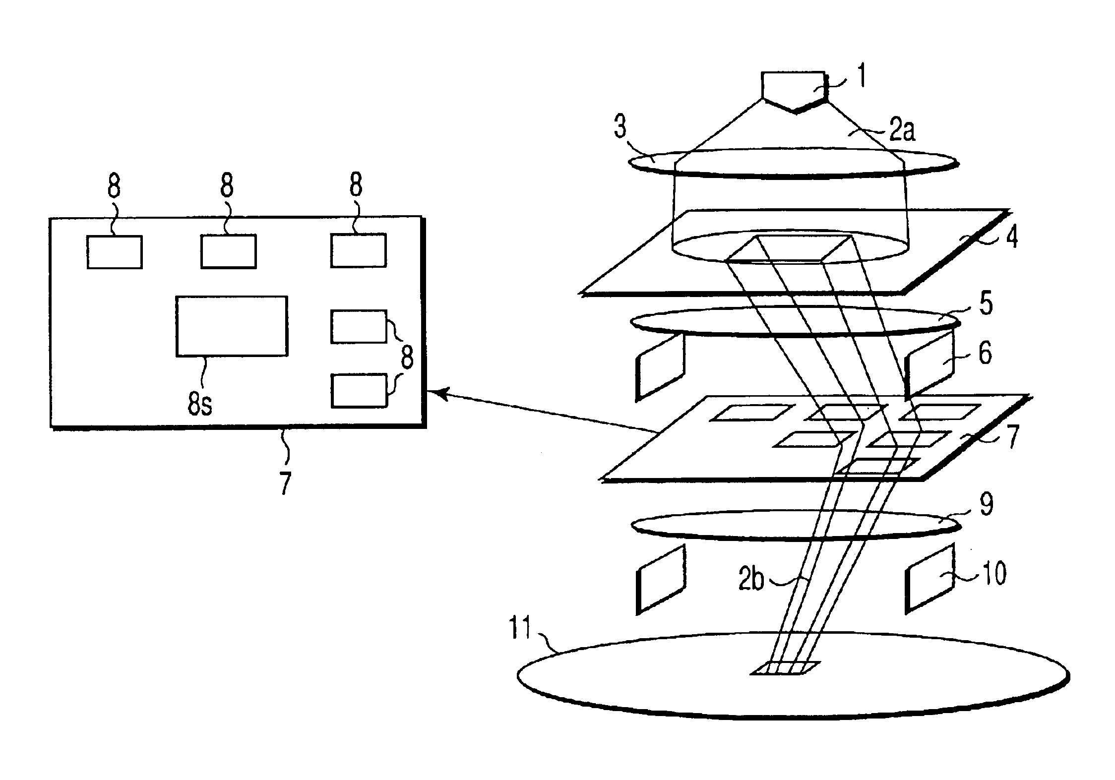
[0062]FIG. 1 is a schematic structural diagram of an exposure apparatus according to a first embodiment of the present invention. In the following description of embodiments, same reference numerals refer to same components, and specific explanation is omitted.

[0063]The exposure apparatus of this embodiment is a CP and variable shape type electron beam exposure apparatus having an acceleration voltage of 5 keV. The value of the acceleration voltage is not limited to 5 keV.

[0064]In FIG. 1, reference numeral 1 is an electron gun, and an electron beam 2a generated from the electron gun 1 passes through a lens 3, a first aperture mask 4, and a lens 5, and is emitted to a desired position on a second aperture mask 7 (CP aperture mask) by means of a deflector 6. An opening for pattern (CP pattern) 8 is provided in the CP aperture mask 7. In FIG. 1, reference numeral 8s shows a square opening.

[0065]In this apparatus, the number of CP patterns 8 is 400 (only part is shown)...

second embodiment

(Second Embodiment)

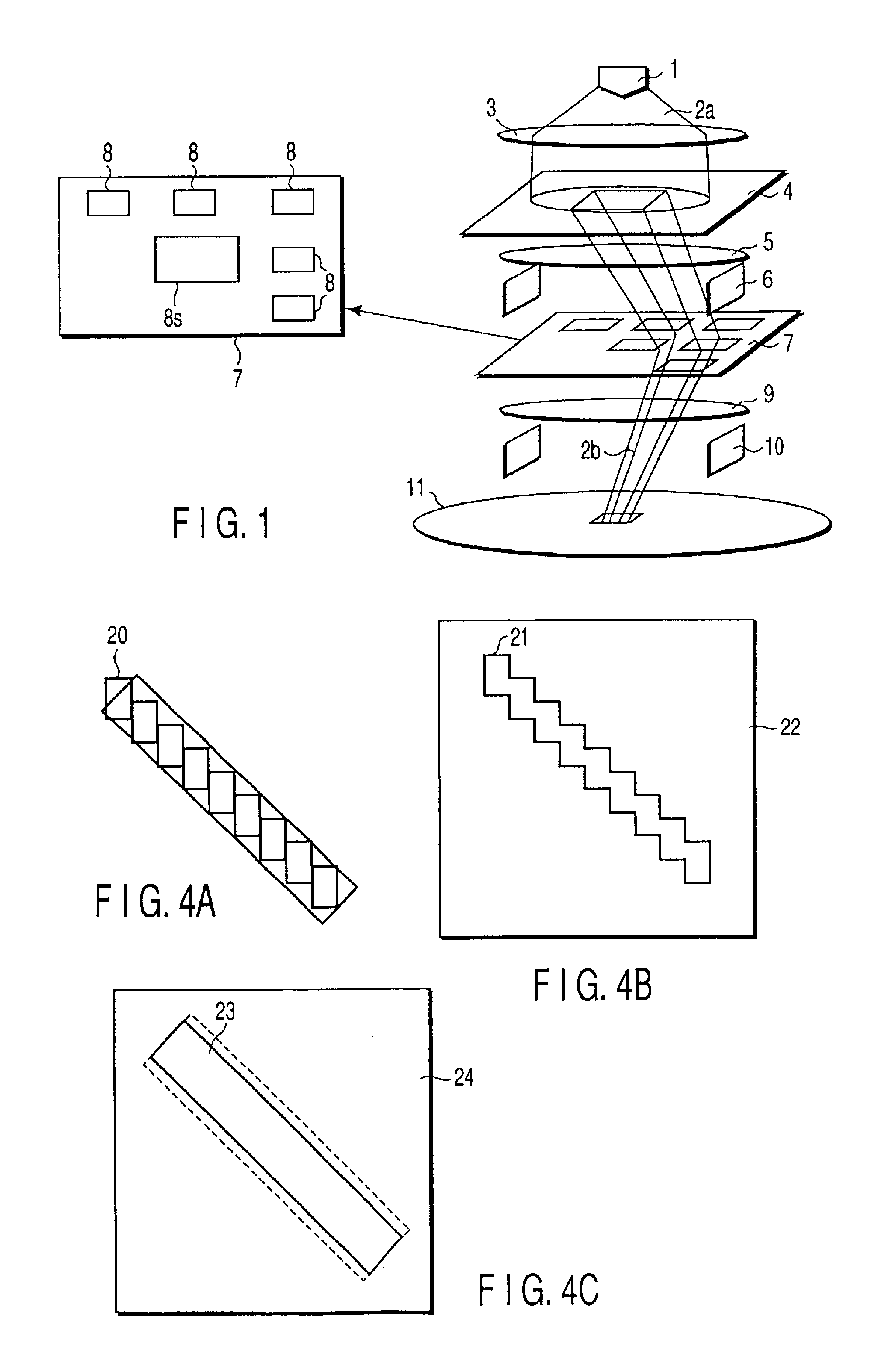
[0090]FIG. 4A to FIG. 4C are diagrams explaining a method of forming an oblique line pattern according to a second embodiment of the invention.

[0091]When forming a 45-degree oblique line by using a square beam, exposure is carried out as shown in FIG. 4A. Considering the beam blur of square beam 20 in the X- and Y-directions such that the width of the 45-degree oblique line may be a designed value, the aspect ratio of square beam 20 in the X- and Y-directions is set, and exposure is carried out while stepping the square beam 20 in a 45-degree direction. Meanwhile, the X-direction is the lateral direction in the diagram, and the Y-direction is a vertical direction in the drawing, being perpendicular to the X-direction (same in the following description).

[0092]To securely prevent occurrence of gap between the square beams 20, when stepping while overlapping the square beam 20, the aspect ratio of the square beam 20 in the X- and Y-direction is set in consideration o...

third embodiment

(Third Embodiment)

[0098]FIG. 5A to FIG. 5C are diagrams explaining an exposure method according to a third embodiment of the invention. This is to explain an EB exposure method using a CP aperture mask processed by thinning.

[0099]FIG. 5A shows a conventional CP pattern (original diagram) 30 without thinning process and the beam intensity distribution on the wafer (sample) using it.

[0100]In this embodiment, as shown in FIG. 5B, the CP pattern (original diagram) is thinned in the X-direction, and the obtained CP pattern 31 is used. In this case, when the pattern is formed in the same exposure amount as in the prior art, the beam intensity is weaker on the wafer by the thinned portion, and the pattern width on the wafer is narrower.

[0101]Accordingly, in the embodiment, as shown in FIG. 5C, by heightening the peak value of the beam intensity and increasing the exposure amount than conventional method, a pattern 32 is formed on the wafer exactly in the designed size.

[0102]Preferably, the...


PUM

PropertyMeasurementUnit
aspect ratioaaaaaaaaaa
energyaaaaaaaaaa

Abstract

An exposure method using an energy beam exposure apparatus capable of controlling magnitude relation between blurs of energy beam in first and second directions for exposing a pattern on a sample in the apparatus in a state in which the blur of energy beam in one direction of the first and second directions is set smaller than the blur of energy beam in the other direction comprises adjusting the magnitude relation of the blurs of energy beam in the first and second directions, adjusting the direction of the sample in the apparatus on the basis of the pattern and the magnitude relation of the blurs of energy beam in the first and second directions, and projecting the pattern onto the sample by exposing the sample to the energy beam and using shape correction of the pattern needed to compensate blurs of energy beam in the first and second directions.

Description

CROSS-REFERENCE TO RELATED APPLICATIONS[0001]This application is based upon and claims the benefit of priority from the prior Japanese Patent Application No. 2002-151312, filed May 24, 2002, the entire contents of which are incorporated herein by reference.BACKGROUND OF THE INVENTION[0002]1. Field of the Invention[0003]The present invention relates to an energy beam exposure method and an exposure apparatus for use in manufacture of a semiconductor device.[0004]2. Description of the Related Art[0005]Recently, as large scale integrated circuits (LSI) are becoming higher in density, electron beam exposure (EB exposure) is actually used. One type of EB exposure is character projection exposure (CP exposure) which is a kind of partial batch exposure. In this system (CP system), from an aperture mask (CP aperture mask) having plural character projection patterns (CP patterns), a desired CP pattern is selected, and the electron beam having passed through this selected CP pattern is reduce...

Claims


Application Information

Patent Timeline
Patent Type & Authority Patents(United States)
IPC IPC(8): G03F7/20H01J37/317G03F1/20G03F1/68H01L21/027
CPCB82Y10/00B82Y40/00G03F7/70441H01J37/3174G03F7/70475H01J2237/31776H01J2237/31761H01L21/027
Inventor SASAKI, NORIAKINAKASUGI, TETSURO
Owner KK TOSHIBA
Why Eureka
Try Eureka