Brushless motor

a brushless motor and motor housing technology, applied in the direction of dynamo-electric machines, electrical equipment, magnetic circuit shapes/forms/construction, etc., can solve the problems of inability to infinitely increase the number of slots, degrade steering feeling of the driver of the automobile, and so on, so on. , to achieve the effect of suppressing demagnetization, reducing the influence of armature reaction, and large magnetic path resistan

Active Publication Date: 2005-05-24
MITSUBA CORP
View PDF3 Cites 18 Cited by
  • Summary
  • Abstract
  • Description
  • Claims
  • Application Information

AI Technical Summary

Benefits of technology

[0011]In a brushless motor according to the invention, the center of each of the auxiliary grooves of each of the teeth may be located on a radial line extended from the corresponding circumferential end face of the teeth. The position that is located on a radial line extended from the circumferential end face of the tooth is a position where the magnetic flux shows a high density along the front end of the tooth. Therefore, as the center of each of the auxiliary grooves is located on the position, the magnetic path of the reactive magnetic flux of the armature is narrowed and the magnetic path resistance becomes large. Accordingly, the reactive magnetic flux of the armature can hardly flow through the teeth to consequently reduce the influence of the armature reaction. Hence, it is now possible suppress demagnetization.
[0012]Additionally, in a brushless motor according to the invention, the auxiliary grooves may be made to have a width equal to the width of the slots separating adjacent teeth. With this arrangement, the sub-teeth produced by the auxiliary grooves at the front ends of the teeth are arranged peripherally at regular intervals to apparently increase the number of slots of the stator core.
[0013]A brushless motor according to the invention may be used as drive source of an electric power steering device. Then, noises and vibrations attributable to cogging can be reduced and the operation of steering the automobile is made very smooth to give the driver of the automobile good steering feeling.

Problems solved by technology

However, a so-called cogging torque can easily arise in brushless motors due to the attractive force between the permanent magnet at the rotor side and the core teeth at the stator side.
The cogging torque can cause noises and vibrations and, in the case of the EPS device of an automobile, it can degrade steering feeling to the driver of the automobile.
However, it is not possible to infinitely increase the number of slots and hence the effect of a multi-slot stator is limited by the size of the motor.
In other words, part of the magnetic flux does not pass through the front ends of the teeth and the cogging reducing effect of the pseudo-slots is not fully achieved because of the part of the magnetic flux unrelated to the auxiliary grooves.

Method used


Image

  • Brushless motor
  • Brushless motor
  • Brushless motor

Examples


Embodiment Construction

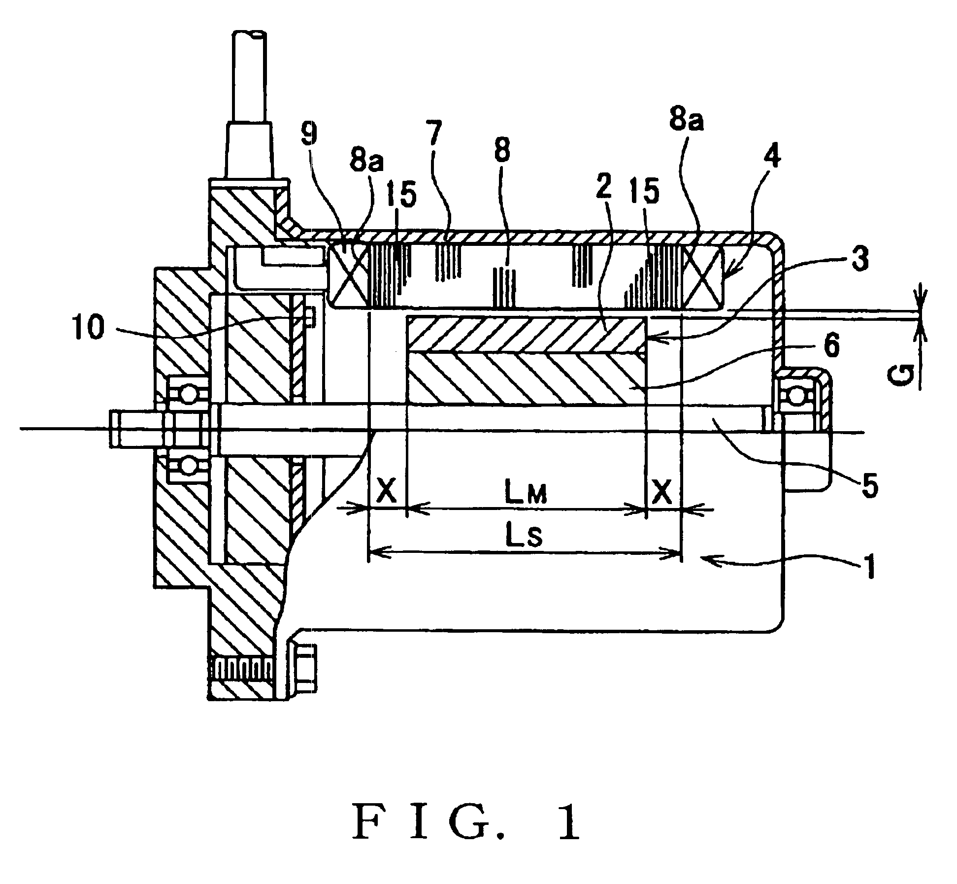
[0021]Now, the present invention will be described in greater detail by referring to the accompanying drawings. FIG. 1 is a schematic illustration of an embodiment of a brushless motor according to the invention, showing its configuration. The illustrated brushless motor 1 (to be referred to simply as motor 1 hereinafter) is designed to operate as drive source of an EPS device. As shown in FIG. 1, the brushless motor 1 is of the inner rotor type and comprises a rotor 3 having a rotor magnet 2 (to be referred to simply as magnet 2 hereinafter) and a stator 4 arranged around the rotor 3. The motor 1 is driven as the driver of the automobile that is provided with the embodiment operates the steering wheel of the automobile and controlled according to the angle by which the steering column is turned, the running speed of the vehicle and so on so as to apply appropriate steering assisting force to the steering column by way of a reduction gear (not shown).

[0022]The rotor 3 includes a rot...


PUM


Abstract

A brushless motor 1 comprises a rotor 3 having a magnet 2 and a stator 4 having a stator core 8. The stator core 8 has teeth 11 provided at the front ends thereof with auxiliary grooves to realize a pseudo-multi-slot arrangement. The magnet 2 has an axial length of LM while the stator core 8 has an axial length of LS, LS being greater than LM (LS>LM). The stator core 8 is provided at the opposite ends thereof with respective overhanging portions 15 that are not vis-à-vis the magnet 2. As a result, the magnetic flux is prevented from flowing into the stator core 8 through the axial end faces 8a thereof. In other words, the magnetic flux mostly flows into the stator core 8 through the front ends of the teeth. As a result, the pseudo-multi-slot effect produced by the auxiliary grooves is efficiently boosted to reduce cogging and other problems.

Description

BACKGROUND OF THE INVENTION[0001]1. Field of the Invention[0002]This invention relates to a brushless motor and more particularly it relates to a brushless motor adapted to reduce the cogging torque thereof.[0003]2. Related Art Statement[0004]Brushless motors are used abundantly in various industrial fields in recent years because of the advantage that they do not have any mechanical contact point like between the brush and the commutator and therefore they are free from various problems, such as wear of a brush and electric noises. Examples of fields of application of brushless motors include industrial machines such as robots, IT devices such as personal computers and electric power steering (to be referred to as EPS hereinafter) devices for automobiles. Brushless motors are being increasingly used in these fields particularly due to the development of semiconductor control circuits. However, a so-called cogging torque can easily arise in brushless motors due to the attractive for...

Claims


Application Information

Patent Timeline
Patent Type & Authority Patents(United States)
IPC IPC(8): H02K29/03H02K21/16H02K1/14H02K29/00
CPCH02K29/03H02K21/16
Inventor OKUBO, MASAYUKI
Owner MITSUBA CORP
Why Eureka
Try Eureka