Magnetic energy storage device

a magnetic energy storage and magnetic technology, applied in the direction of superconducting magnets/coils, magnetic bodies, instruments, etc., can solve the problems of one feed-through current-carrying lead, small loss, and long storage tim

Inactive Publication Date: 2005-05-24
ABB (SCHWEIZ) AG
View PDF4 Cites 6 Cited by
  • Summary
  • Abstract
  • Description
  • Claims
  • Application Information

AI Technical Summary

Problems solved by technology

Since the coil is superconducting, very small losses are present and the storage time is very long.
The design of such feed-through current-carrying leads is one of the main difficulties when constructing a SMES device.
However, a good electrical conductor is generally also a very good heat conductor, which makes the thermal isolation of the cold space difficult.
Another drawback with using conventional switches is that the switches always exhibit resistive losses since it is practically impossible to construct a

Method used


Image

  • Magnetic energy storage device
  • Magnetic energy storage device
  • Magnetic energy storage device

Examples


Embodiment Construction

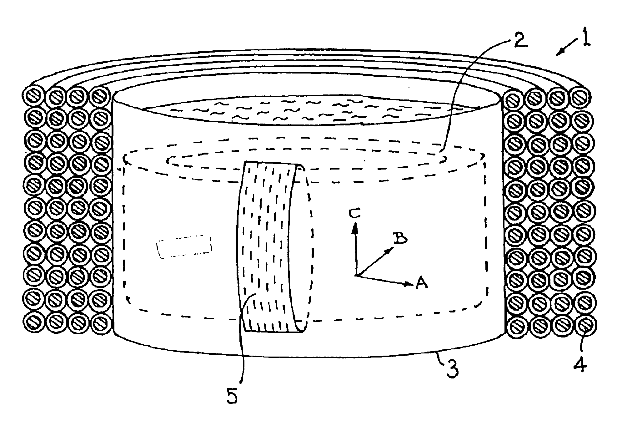
[0028]FIG. 1 shows one embodiment of a SMES according to the invention and generally designated by the reference numeral 1. The SMES 1 comprises a one turn first coil in the form of a cylinder 2 and made of superconducting material, such as YBCO having a Tc=92 K. The cylinder 2 forms a closed electric circuit and has no mechanical or physical connections connected thereto for supplying energy to or extracting energy from the coil. The cylinder 2 is cooled to superconducting temperatures by cryogenic cooling means. In the embodiment shown, the cylinder 2 is received in a container 3, e.g. a conventional dewar, containing liquid nitrogen at a temperature of 77 K. Alternatively a suitable enclosure means for containment and circulation of helium (or other coolant) in a gas, liquid or gas / liquid mixture may be used. Cooling down to between 40 K and 20 K or less in this manner provides a higher magnetic flux density in high temperature superconductors such as YBCO or BSCCO.

[0029]A second...


PUM


Abstract

A superconducting magnetic energy storage (SMES) device including a first coil made of superconducting material, a cooling mechanism for cooling the first coil to superconducting temperatures, a second coil inductively coupled to the first coil for inputting emergy to, and/or outputting energy from, the first coil, and a switch for switching the first coil between a superconducting condition and a non-superconducting condition. The first coil is arranged as a closed loop electric circuit having no connecting device mechanically connected to it for inputting or outputting energy. The switch includes a third coil for the application or removal of a magnetic field for switching the first coil between its non-superconducting and superconducting conditions. A method inputs energy to and/or outputs energy from the first coil and a power supply system utilizes the device and method.

Description

TECHNICAL FIELD[0001]This invention relates to a superconducting magnetic energy storage (SMES) device of the kind comprising a closed first coil means made of superconducting material, cooling means for cooling the first coil to superconducting temperatures, second coil means inductively coupled to the first coil means for inputting energy to, and / or outputting energy from the first coil means, and switching means for switching the first coil means between a superconducting condition and a non-superconducting condition. Although the invention primarily relates to a SMES device in which the first coil means comprises a high-transition temperature superconducting (HTS) material it also relates to a SMES device in which the first coil means comprises a low-transition temperature superconducting (LTS) material. The invention also relates to a method of inputting and outputting energy to and from a network and to a network protection system.[0002]The invention has application in maintai...

Claims


Application Information

Patent Timeline
IPC IPC(8): H01F6/00H02J15/00H01F6/04
CPCH01F6/006H02J15/00Y10S505/879Y10S505/869Y10S505/70H02J2310/40
Inventor JONSSON, TOMASTHORBURN, KARINFROMM, UDOHESSLING, PETERGUSTAFSSON, ARNESASSE, CHRISTIANMIN, PANDAHLGREN, MIKAEL
Owner ABB (SCHWEIZ) AG
Why Eureka
Try Eureka