Electrophoretic display device

a display device and display panel technology, applied in the direction of fluid pressure measurement, liquid/fluent solid measurement, peptides, etc., can solve the problems of difficult to see characters on the display panel, insufficiently solved problems, and heavy eye strain

Inactive Publication Date: 2005-05-24
CANON KK
View PDF24 Cites 36 Cited by
  • Summary
  • Abstract
  • Description
  • Claims
  • Application Information

AI Technical Summary

Problems solved by technology

The current liquid crystal display devices, however, have the problem that characters on a display panel become harder to see, depending upon angles of view to the display panel and upon reflected light, and the problem that strain is heavy on the eyes because of flickering of the light source, low luminance, and so on.
These problems have not been adequately solved yet.
The color coupler is thus likely to act as a destabilizing factor in the electrophoretic operation and sometimes degraded the performance, lifetime, and stability of the display device.
The electrophoretic display device described above, however, had the following problems.
This viewing angle d

Method used


Image

  • Electrophoretic display device
  • Electrophoretic display device
  • Electrophoretic display device

Examples


example 1

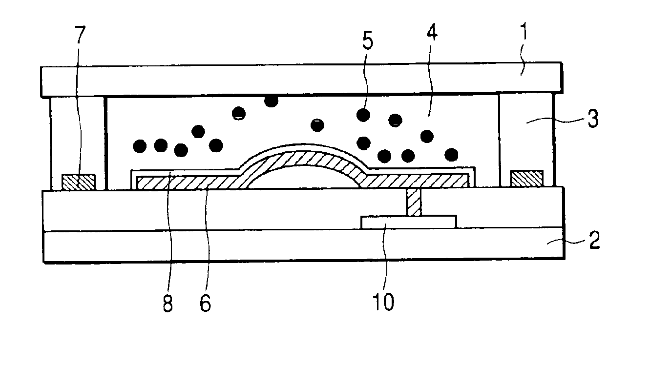
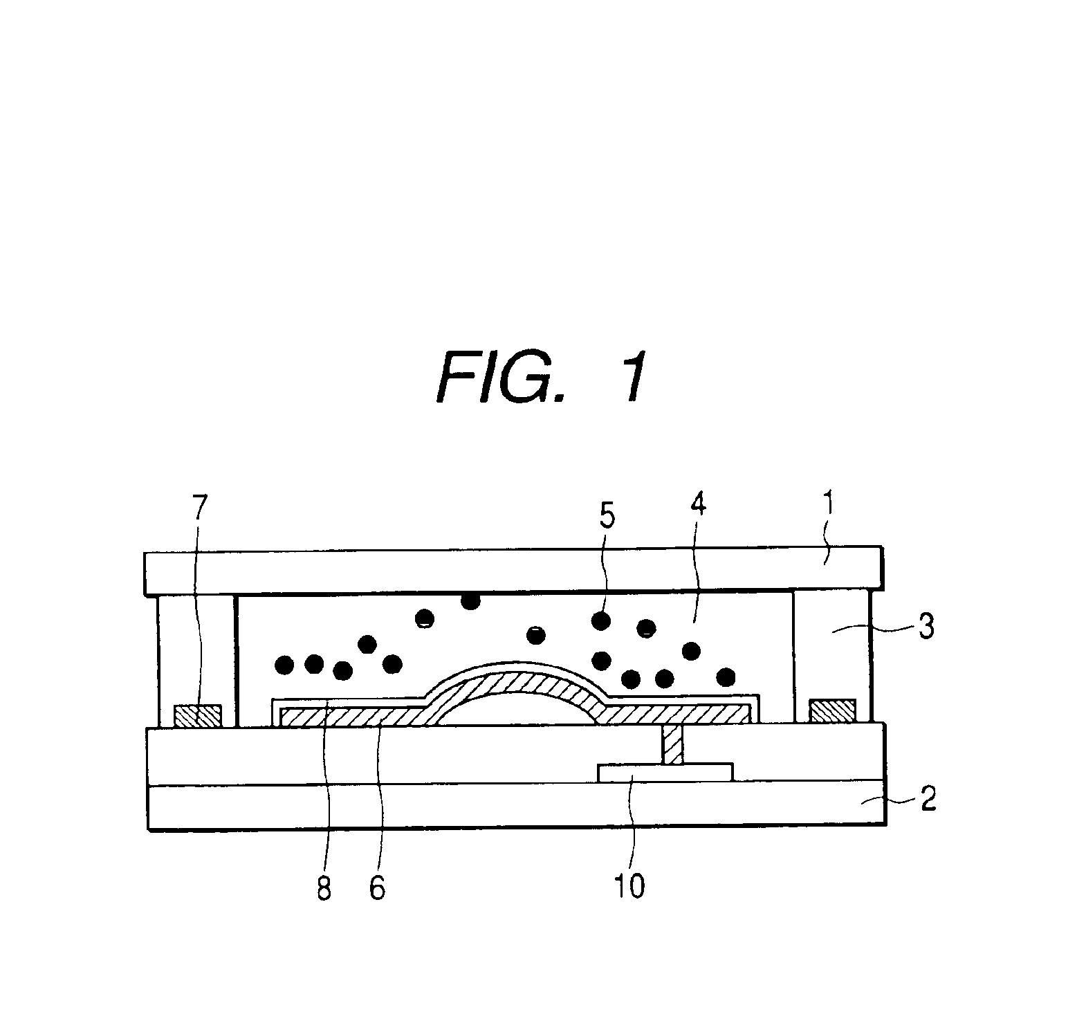
[0077]The present example will describe a method of fabricating the electrophoretic display device shown in FIG. 1. The display device to be fabricated includes 200×200 pixels and the size of each pixel is 120 μm×120 μm. The cell wall surrounds each pixel at the periphery thereof. The cell wall is structured in the width (or thickness) of 10 μm and in the height of 20 μm. The first electrode of each pixel is located in the central region of the portion surrounded by the cell wall and the length of each edge is 100 μm. Furthermore, the central region of the first electrode has a protruding structure. The protrusion is shaped in the height of 10 μm and in the length of each edge of 20 μm. The surface of the protrusion is a curved surface. The second electrode of each pixel is located on the bottom surface of the cell wall, i.e., between the rear-side substrate and the cell wall.

[0078]The following will describe the method of producing the electrophoretic display device according to th...

example 2

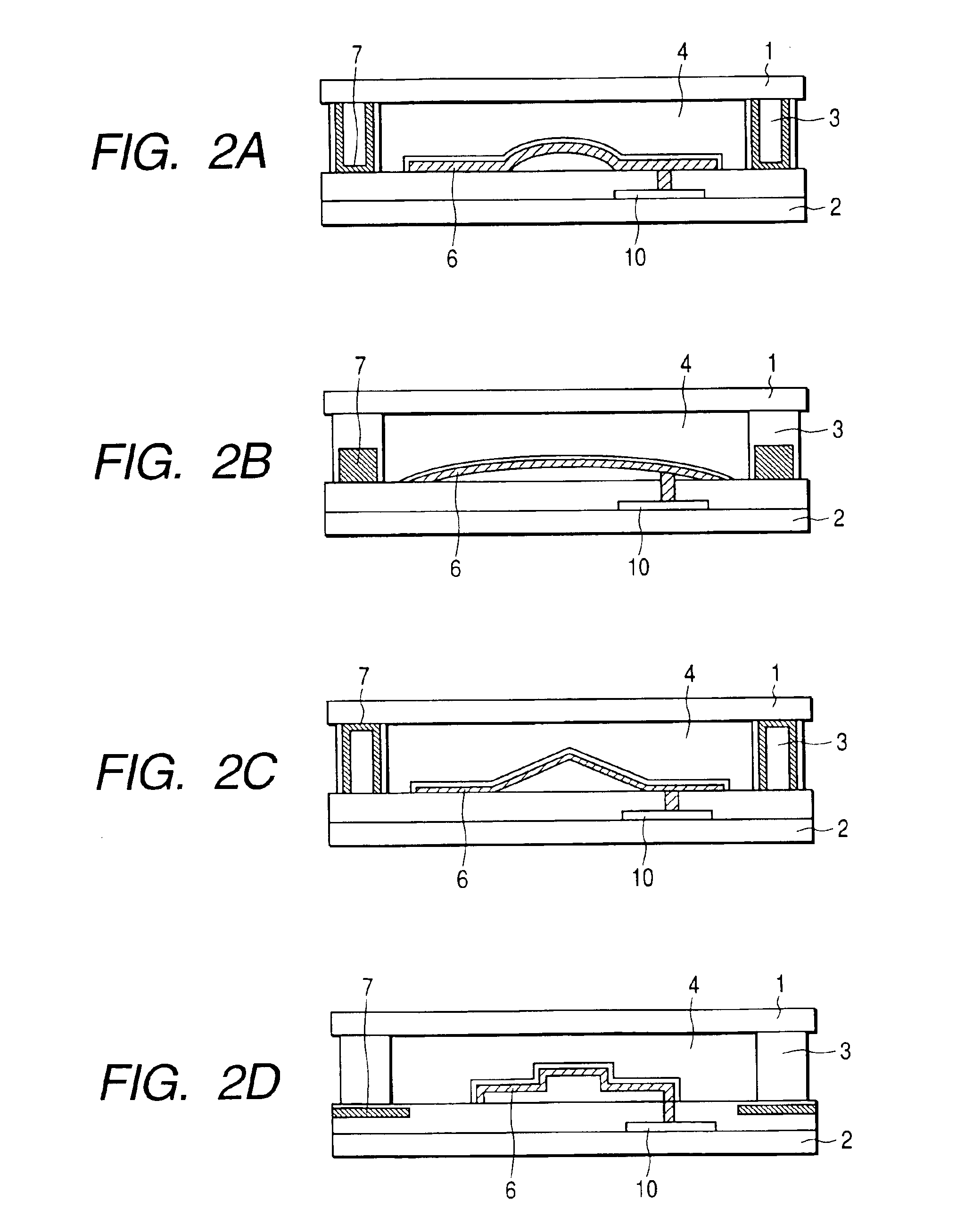
[0083]In the present example the electrophoretic display device shown in FIG. 2A is fabricated in a method similar to that in Example 1.

[0084]The present example is characterized in that each second electrode is formed on the side and the bottom faces of the cell wall. The shape of the first electrodes and others are substantially the same as those in Example 1. When the second electrode is formed on the side face of the cell wall, the electric field becomes stronger and more uniform in each pixel space surrounded by the display-side and the rear-side substrates and the cell wall, so that the particles that cause the degradation of the contrast by remaining in the central region of each pixel during the display operation, e.g., during the white display, can be reduced greatly.

example 3

[0085]In the present example, the electrophoretic display devices with the structures of the first electrode shown in FIGS. 2B, 2C, and 2D are fabricated. FIG. 2B shows the structure in which the protrusion is formed over the entire surface of the first electrode and in which the second electrode is formed inside the cell wall. FIG. 2C shows the structure in which the central region of the protruding portion of the first electrode is angled so as to facilitate orientation of electric field vectors toward the second electrode and in which the second electrode is formed on the side and the top faces of the cell wall. FIG. 2D shows the structure in which the protruding portion is formed stepwise in the central region of the first electrode and in which the second electrode is formed inside the rear-side substrate. These structures exhibit the effects similar to those in Example 1.

[0086]Because the central part of each display pixel is protruding toward the display surface, the light as...


PUM

PropertyMeasurementUnit
Heightaaaaaaaaaa
Heightaaaaaaaaaa
Coloraaaaaaaaaa

Abstract

An electrophoretic display device is configured to move charged particles between a display electrode surface and a cell wall surface and provides a solution to a problem that many charged particles are collected at the edge of the display electrode to degrade display contrast. The electrophoretic display device is arranged to move the charged particles between the display electrode surface and the side face of the cell wall and the vicinity thereof to implement display, and the second electrode is disposed on a lower face of the cell wall or in the vicinity of the lower face, thereby allowing the particles to be located on the surface of the cell wall. Another electrophoretic display device is provided which has a structure wherein all or part of the display electrode has a protruding shape.

Description

BACKGROUND OF THE INVENTION[0001]1. Field of the Invention[0002]The present invention relates to an electrophoretic display device configured to implement display on the basis of migration of charged particles in a dispersing fluid.[0003]2. Related Background Art[0004]In recent years, proposals have been made on various types of electrophoretic display devices configured to implement display on the basis of migration of charged particles in a dispersing fluid. The electrophoretic display device will be described below.[0005]With development of information equipment, there are increasing needs for low-power-consumption and low-profile display devices, and research and development is active on the display device to meet these needs. Among others, the liquid crystal display devices are actively developed and commercially available as display devices capable of meeting such needs. The current liquid crystal display devices, however, have the problem that characters on a display panel be...

Claims


Application Information

Patent Timeline
IPC IPC(8): G02F1/01G02F1/167G02F1/1679
CPCG02F1/167G02F1/1679
Inventor IKEDA, TSUTOMUUKIGAYA, NOBUTAKAISHIGE, KOICHI
Owner CANON KK
Why Eureka
Try Eureka