

Process cartridge and electrophotographic image forming apparatus
a technology of electrophotographic image and cartridge, which is applied in the direction of electrographic process apparatus, instruments, optics, etc., can solve the problems of complex communication structure between the main body of the electrophotographic image forming apparatus and the contact portion of the memory in the cartridge, and achieve the effect of simple structur
- Summary
- Abstract
- Description
- Claims
- Application Information
AI Technical Summary
Benefits of technology
Problems solved by technology
Method used
Image

Examples
embodiment 1
(Embodiment 1)
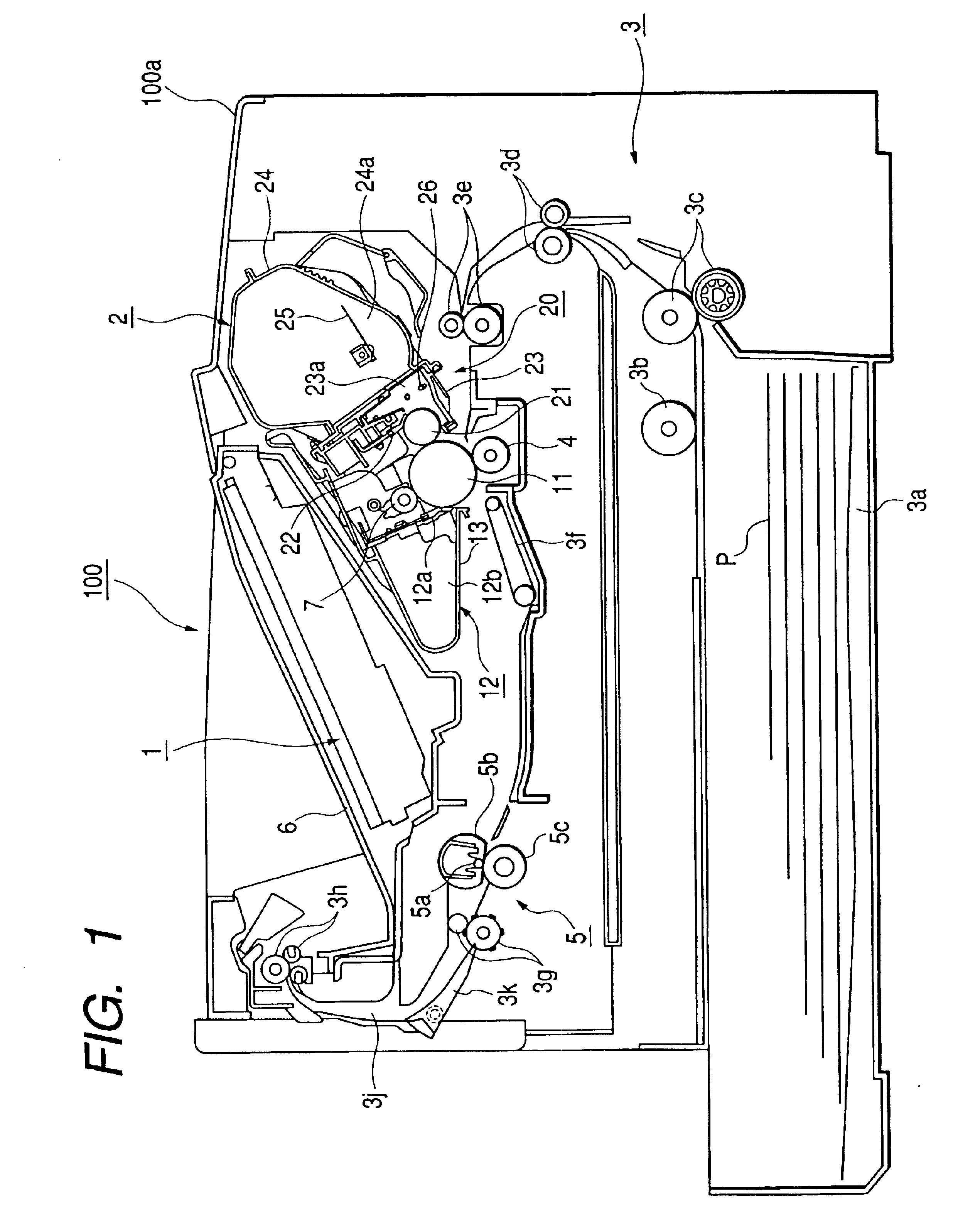
[0084]FIG. 1 shows the electrophotographic image forming apparatus according to a first embodiment. This apparatus comprises optical means 1 including a laser diode, a polygon mirror, a lens, and a reflective mirror. The optical means 1 produces a laser beam according to image information. Owing to this, a latent image according to the image information is formed on a photosensitive drum 11 that is an electrophotographic photosensitive body of a process cartridge 2. This latent image is developed by developing means to be made a visible image, i.e., a toner image.
(Whole Structure of Image Forming Apparatus)
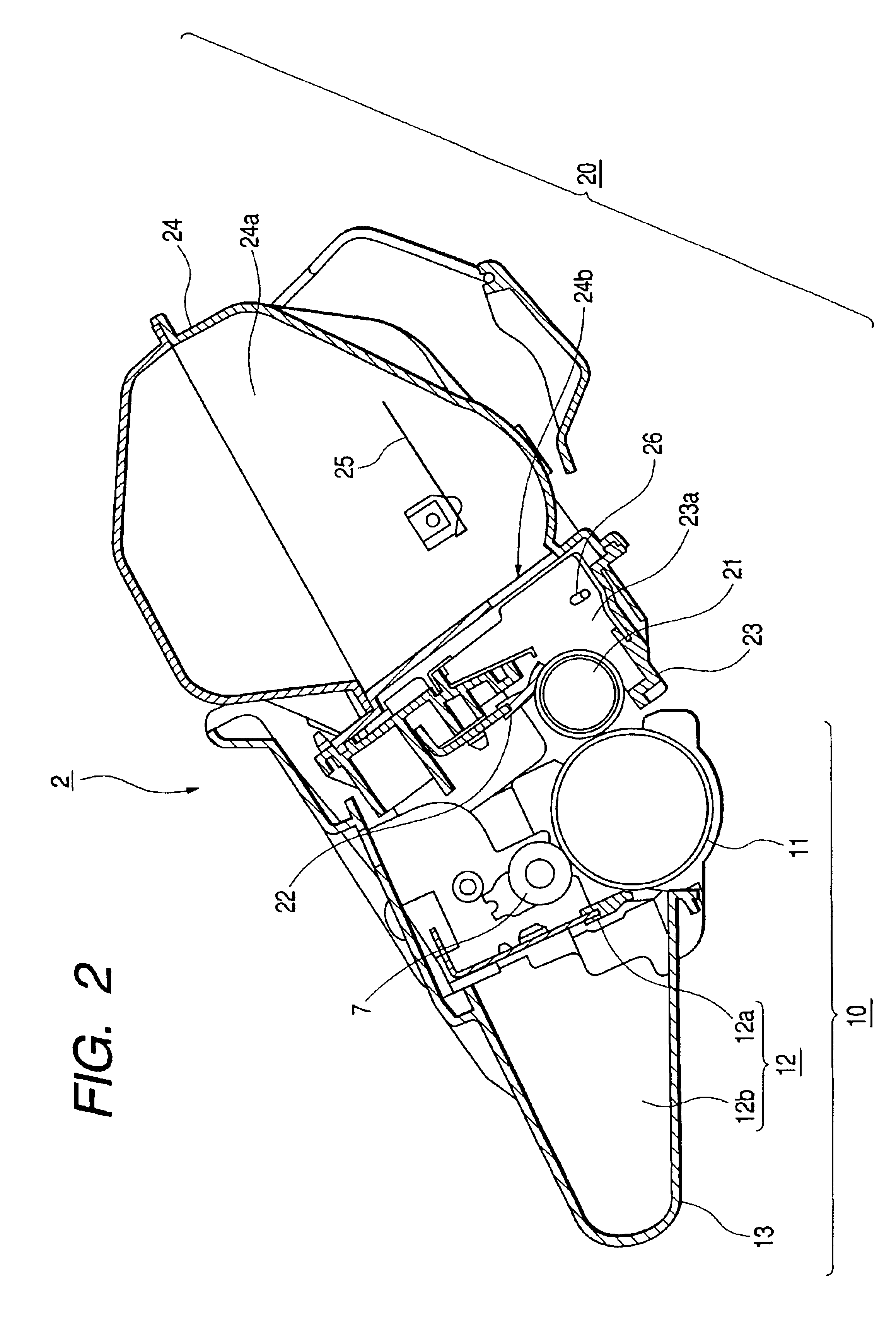
[0085]Developing means that is one of process means for image formation comprises a developing roller 21 that is a developer bearing body that sends out toner to the photosensitive drum 11, and a developing blade 22 that is a regulating member for regulating the quantity of developer adhering to a surface of the developing roller 21. In addition, by combining the dev...
embodiment 2
(Embodiment 2)
[0138]In this embodiment, only items different from those in the above-mentioned first embodiment will be explained, and the explanation of the other structure similar to that of the first embodiment will be omitted.
[0139]Next, the structure of the connector arranged in the main body will be explained.
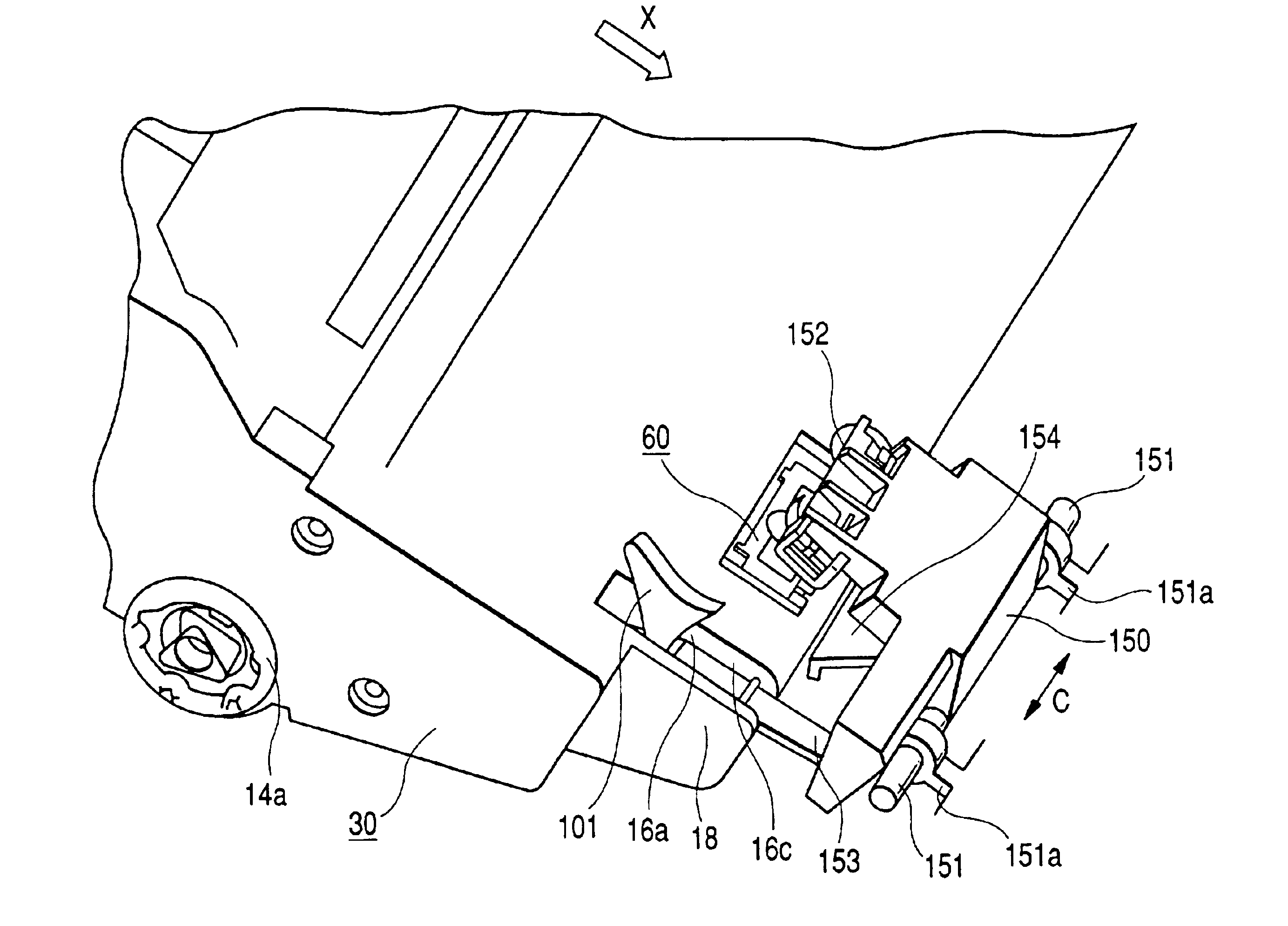
[0140]As shown in FIGS. 20 and 21, one or two electrical contacts 142 that are metallic main body electrical contacts generating contact pressure by elastic deformation are arranged in the connector 140 per contact portion 62 of the memory tag 60. Beside the electrical contact 142, the bumping portions 141 abutting on the abutting portion 63 (refer to FIGS. 7 and 9) of the memory tag 60 are provided in the vicinity of both sides in the longitudinal direction respectively. In the opposite side of a contact portion of the electrical contact 142 to the memory tag 60, a lead wire is connected to a control unit (not shown) of the main body 100.
[0141]The connector holder 150 co...
embodiment 3
(Embodiment 3)
[0154]In this embodiment, only items different from those in the above-mentioned first and second embodiments will be explained, and the explanation of the other structure similar to that of the first embodiment will be omitted.
[0155]Next, the structure of a connector arranged in the main body 100 will be explained.
[0156]As shown in FIG. 27, one or two electrical contacts 142 that are metallic main body electrical contacts generating contact pressure by elastic deformation are arranged in the connector 140 per contact portion 62 of the memory tag 60. In sides of the electrical contact 142, the bumping portions 141 abutting on the abutting portion 63 (refer to FIGS. 7 and 9) of the memory tag 60 are provided in the vicinity of both sides in the longitudinal direction respectively. In the opposite side of a contact portion of the electrical contact 142 to the memory tag 60, a lead wire is connected to a control unit (not shown) of the main body 100.
[0157]The connector ho...
PUM
 Abstract
Description
Claims
Application Information