Heat sink with guiding fins

a technology of heat sinks and fins, which is applied in the direction of electrical apparatus construction details, lighting and heating apparatuses, basic electric elements, etc., can solve the problems of insufficient wind pressure, inability to achieve good heat dissipation on actual use, and insufficient wind resistance of heat sinks, so as to achieve better heat dissipation of the present invention, the effect of wind resistance is smaller and the flow resistance is smaller

Inactive Publication Date: 2005-05-31
DATECH TECH CO LTD
View PDF9 Cites 21 Cited by
  • Summary
  • Abstract
  • Description
  • Claims
  • Application Information

AI Technical Summary

Benefits of technology

[0008]Therefore, the purpose of the present invention is to produce a heat sink with guiding fins which guides the flow generated by a fan to form a streamline through the declining parts on both sides of the base and the concave part whose top width is wider than the bottom width. By ding so, the wind resistance of the flow becomes smaller and the heat dissipation of the present invention is better.
[0009]To achieve the above purpose, the present invention comprising a base having a plate part and two declining parts and two groups of fins extended up against the two declining parts. Therein, each side of two opposite sides of the plate part comprises a declining part; a plurality of fins are extended up against each of the declining part; a concave part whose top width is wider than its bottom width is formed by the plate part and the two groups of fins; and, there is a proper gap between each two of the neighboring fins. Accordingly, the flow generated by a fan attached to the heat sink is formed into a streamline and its pressure is bigger so that the wind resistance is smaller and the heat dissipation is better.

Problems solved by technology

Although the heat sink made according to the above process can improve the manufacture method of the heat sink with a plurality of parallel fins or pin fins, the fan of the heat sink only guides the flow to the base through the gaps between the fins so that the wind resistance may be too big and the wind pressure may be quite possible not enough.
So, this kind of heat sink can not achieve good heat dissipation on actual usage.

Method used


Image

  • Heat sink with guiding fins
  • Heat sink with guiding fins
  • Heat sink with guiding fins

Examples


Embodiment Construction

[0018]The following descriptions of the preferred embodiments are provided to understand the features and the structures of the present invention.

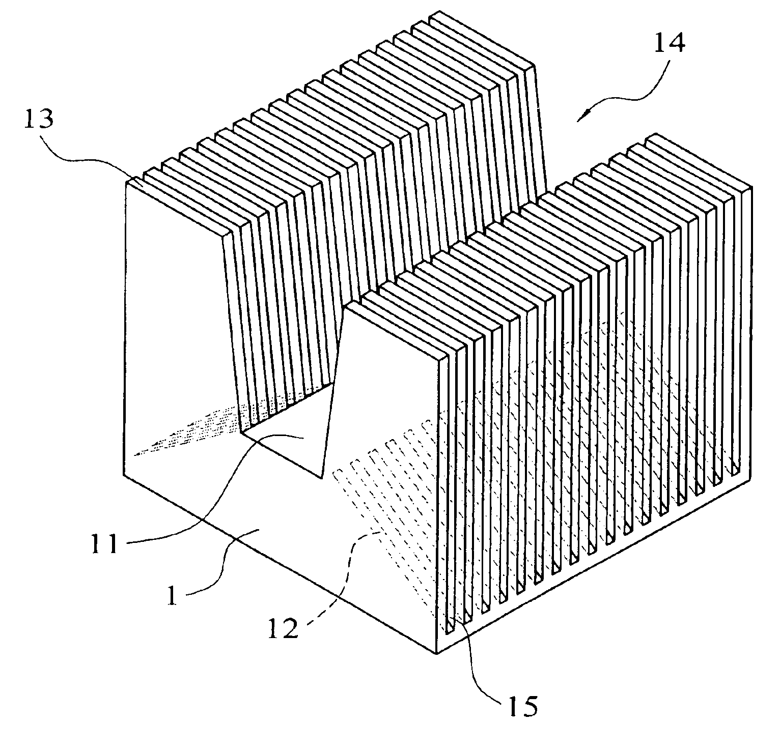
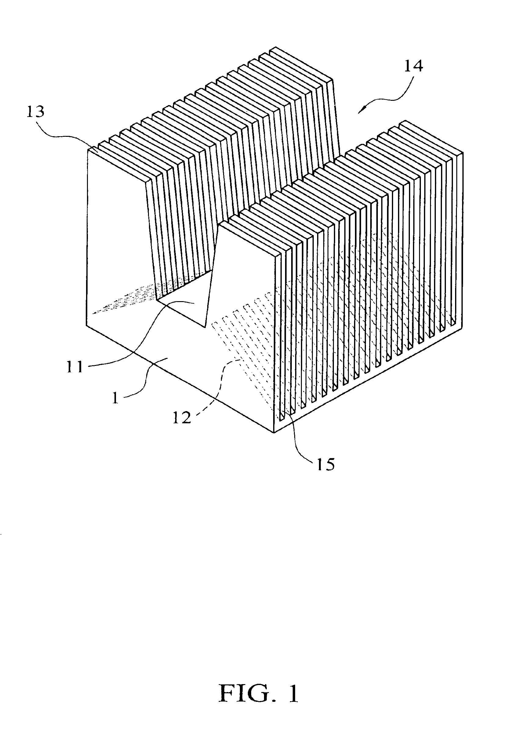
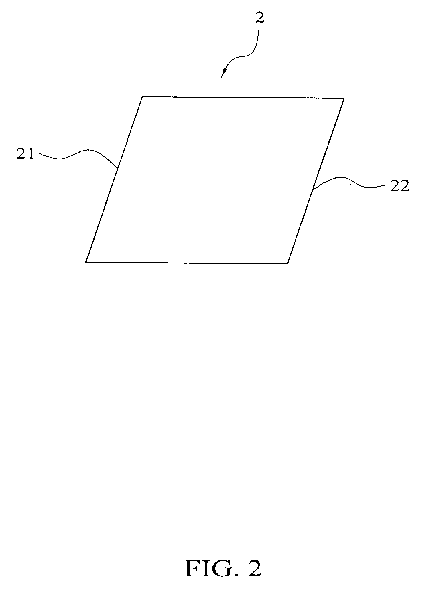
[0019]Please refer to FIG. 1, FIG. 2, FIG. 3, and FIG. 4, which are a perspective view of the first preferred embodiment, a perspective side view of the first preferred embodiment for manufacturing, a perspective view of the metal block of the first preferred embodiment for manufacturing, and a perspective view of the first preferred embodiment showing status on manufacturing according to the present invention. As shown in FIG. 1, the present invention is a heat sink with guiding fins, comprising a base 1 having a plate part 11, wherein each side of a pair of two opposite sides of the plate part 11 comprises a declining part 12; and two groups of fins 13 extended up against the two declining parts 12. The fins 13 and the base 1 can be integrally formed. A concave part 14 whose top width is wider than the bottom width is formed by the plate...


PUM


Abstract

The present invention is a heat sink with guiding fins comprising a base with a plate part, wherein each side of a pair of two opposite sides of the plate part comprises a declining part; and two groups of fins expanded upwardly from each said declining part, wherein a channel whose top width is wider than its bottom width is form by the tow groups of fins and the base and there is a gap properly set between each two fins. By doing so, the heat sink can guide the flow generated by a fan to form a streamline with pressure and so obtains smaller wind resistance and better heat dissipation for the heat sink.

Description

FIELD OF THE INVENTION[0001]The present invention relates to a heat sink with guiding fins. More particularly, the present invention relates to a heat sink with guiding fins which guides the flow generated by a fan attached the heat sink to form a streamline with pressure and so obtains smaller wind resistance and better heat dissipation.DESCRIPTION OF THE PRIOR ART[0002]Accordingly, the process of the prior art like the patent of ‘Process for fabricating heat sink with high-density fins’, U.S. Pat. No. 6,665,933 B2, comprises:[0003](1) providing a metal block comprising a first base being rectangular-solid shaped and a second base being rhombus-shaped and disposed over the first base, wherein the second base comprises a first edge surface and a second edge surface inclined at a specific angle;[0004](2) cutting the second base from a position on the top surface and parallel with the first edge surface until the first base is reached, thereby forming an inclined sheet;[0005](3) adjus...

Claims


Application Information

Patent Timeline
Patent Type & Authority Patents(United States)
IPC IPC(8): H01L21/48H01L21/02H01L23/467H01L23/367H01L23/34
CPCH01L21/4878H01L23/3672H01L23/467H01L2924/0002H01L2924/00
Inventor LI, NIEN-LUNCHU, CHIN-YUEH
Owner DATECH TECH CO LTD
Why Eureka
Try Eureka