
Polarized light source system with mirror and polarization converter

Inactive Publication Date: 2005-05-31
SEIKO EPSON CORP
View PDF26 Cites 39 Cited by
  • Summary
  • Abstract
  • Description
  • Claims
  • Application Information

AI Technical Summary

Problems solved by technology

This results in a dimmer display or requires a brighter light source.
In a projector, a dimmer display is more difficult to view, while a brighter light source increases the power consumption and the cost of the projector system.
The fan adds additional cost, power consumption and noise.
However, it is expensive to produce due to the complex structures required and the precision required to align each of the PBS structures with each lens.
The multi-PBS therefore increases the cost of the projection system.
Another disadvantage of the multiple and single PBS systems comes from a difference in the transmissivity over different incident angles in a typical PBS between horizontal and vertical axes.

Method used


Image

  • Polarized light source system with mirror and polarization converter
  • Polarized light source system with mirror and polarization converter
  • Polarized light source system with mirror and polarization converter

Examples


Embodiment Construction

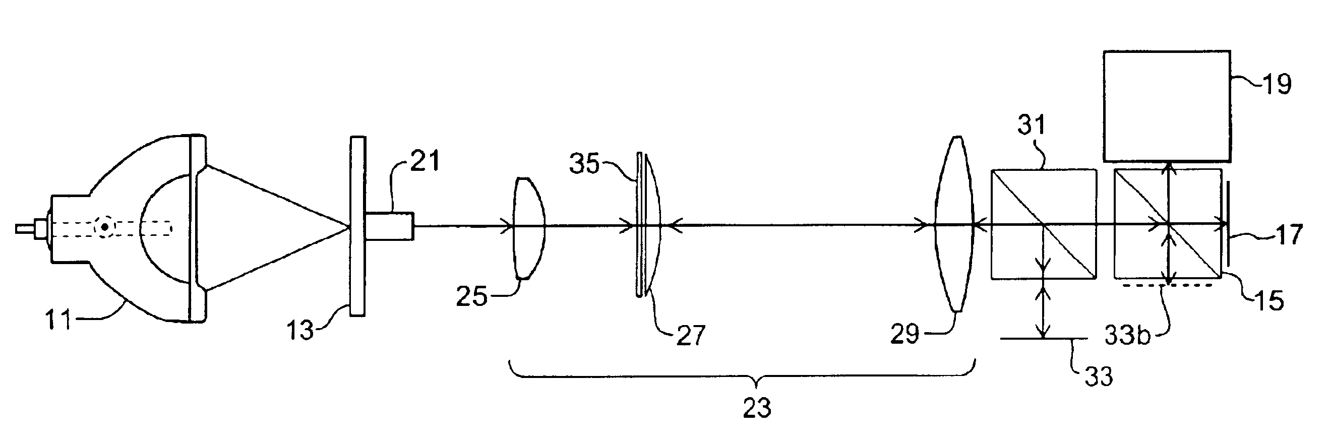
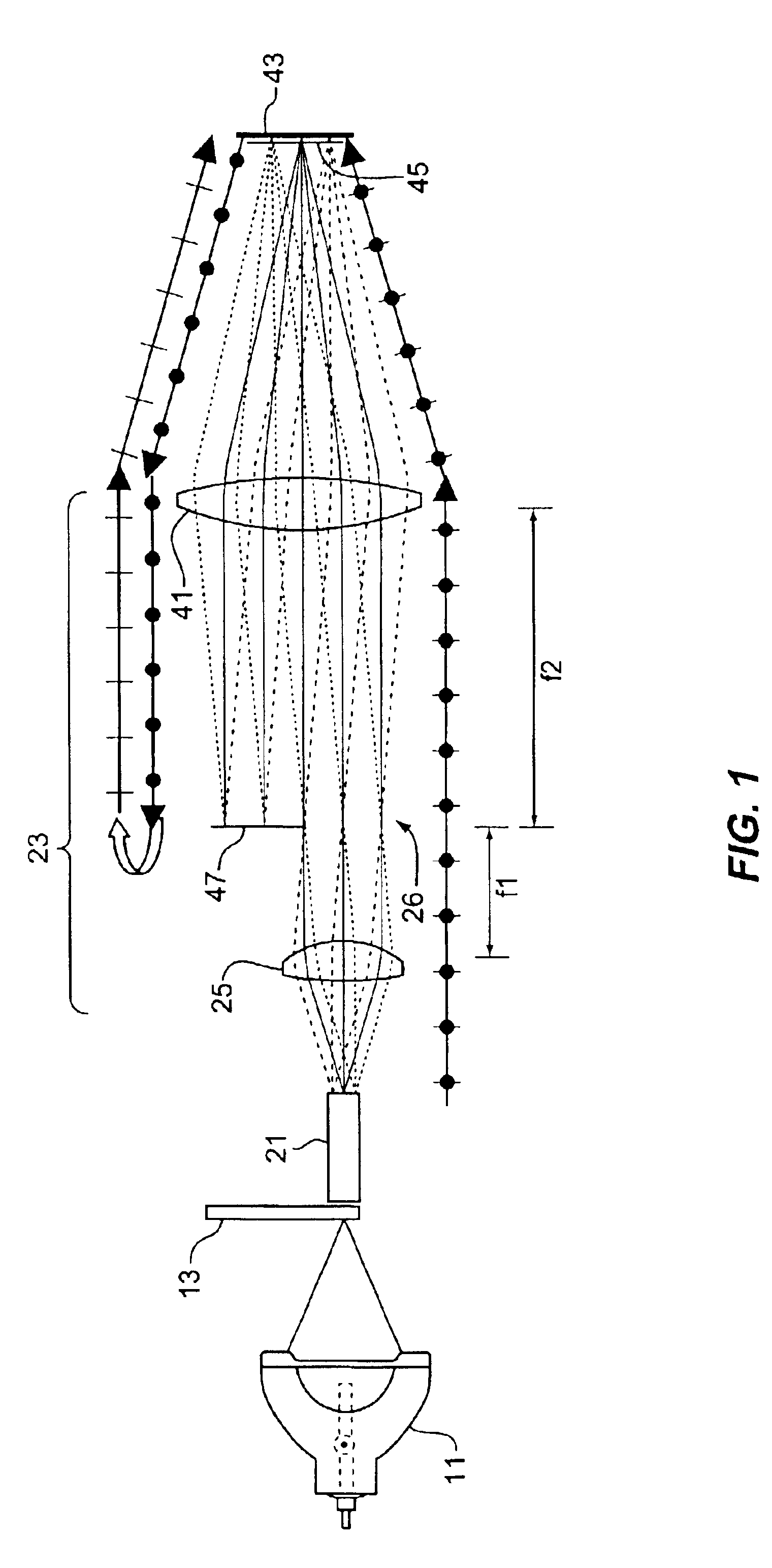
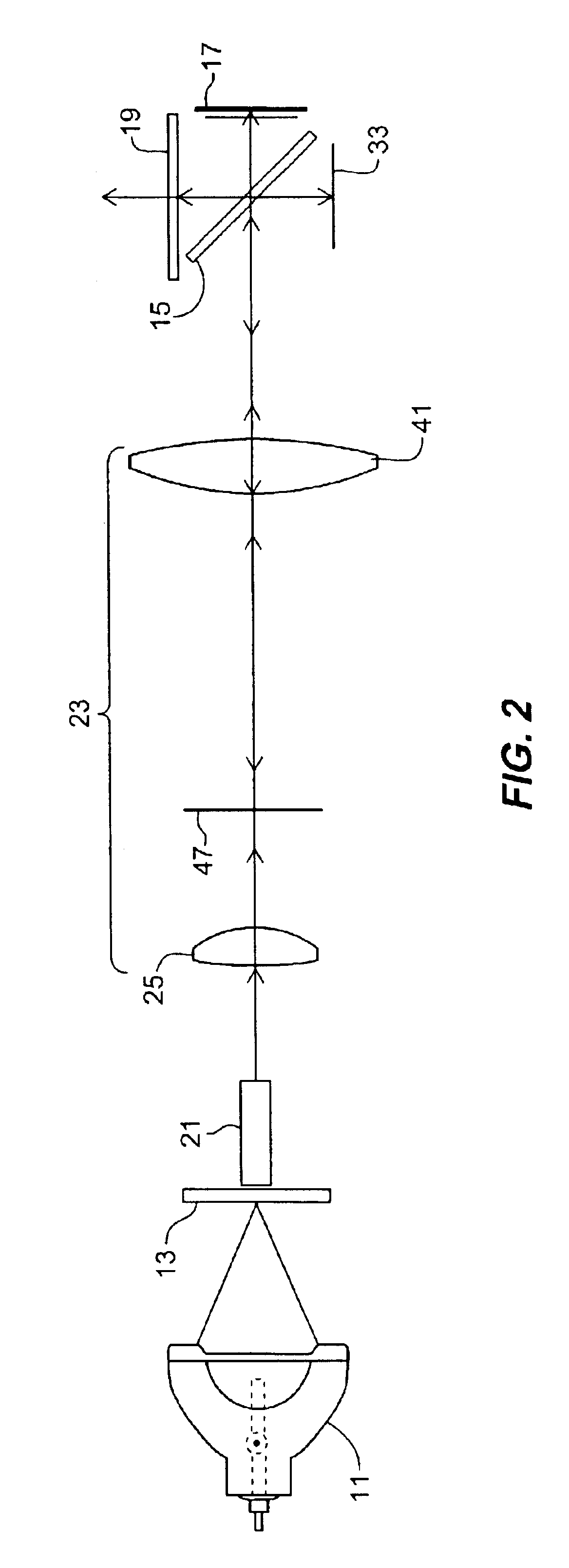
[0019]The present invention provides a less expensive and more efficient illumination source for reflective and transmissive displays using a reverse optical path together with a forward optical path. It also provides an intensity pattern that is spread in one direction, further enhancing efficiency through typical reflective polarizer or PBS (polarizing beam splitter) materials. It can be applied as a PCS (polarization conversion system) for a reflective LCD (liquid crystal display) display in a projector system as well as in many other ways. As a result, lower cost at equal or higher system performance in brightness and contrast can be achieved.

[0020]An example of one embodiment of the present invention is shown in FIG. 1. The embodiment of FIG. 1 is particularly suitable for a projector using transmissive display such as a liquid crystal display or liquid crystal light valve, however any other reflective or transmissive display can be used with appropriate modifications. In the e...


PUM


Abstract

A polarized light source for a display system includes an optical system to image light from a light source onto a display along a first optical path, a reflective polarizer to receive the light from the optical system along a first optical path, direct light of a first polarization of the display, and reflect light of a second polarization along a second optical path separate from the first optical path toward the optical system, a mirror in the second optical path to receive light having the second polarization from the reflective polarizer, and reflect it back to the reflective polarizer, and a polarization conversion system in the second optical path between the reflective polarizer and the mirror to convert the polarization of the reflected light of the second polarization to the first polarization.

Description

BACKGROUND OF THE INVENTION[0001]1. Field of the Invention[0002]The invention relates generally to the field of polarized light sources, such as polarization conversion systems (PCS) for viewing displays directly or by projection. More particularly, the invention relates to a polarized light source with a reverse optical path to enhance brightness.[0003]2. Description of the Related Art[0004]Many displays used in projection and direct viewing systems operate on the basis of polarization. Such displays include reflective displays such as LCoS (Liquid Crystal on Silicon), super twisted nematic (STN), and ferroelectric (FLC) as well as transmissive displays, such as thin film transistor (TFT), poly-silicon (p-si), and Silicon-on-Insulator (SOI). These displays can produce a high resolution image by changing the polarization state upon reflection or transmission of incident light. In an LCoS display, for example, in the dark state, a pixel reflects all light with substantially no change...

Claims


Application Information

Patent Timeline
IPC IPC(8): G02B27/00G02B27/28
CPCG02B27/283
Inventor BIERHUIZEN, SERGE
Owner SEIKO EPSON CORP
Learn More