Immersed membrane apparatus

Inactive Publication Date: 2005-05-31
ZENON TECH PARTNERSHIP
View PDF50 Cites 24 Cited by
  • Summary
  • Abstract
  • Description
  • Claims
  • Application Information

AI Technical Summary

Benefits of technology

[0006]It is an object of the present invention to improve on the prior art. It is another object of the present invention to provide a filtration apparatus comprising a plurality of elements, for example, elements of immersed, suction driven, hollow fibre membranes, mounted to a frame. Embodiments of the invention provide few components to interfere with the flow of tank water through the apparatus, efficient permeate pipe connections, elements that may be removed easily and without interfering with adjacent elements, elements that may be economically manufactured to a wide range of sizes, an apparatus that may be assembled with variable spacing between elements, and a distance between headers of the elements that can be altered to account for membrane shrinkage in use. The objects of the invention are met by the combinations of features, steps or both described in the claims. The following summary may not describe all necessary features of the invention which may reside in a sub-combination of the following features or in a combination of some or all of the following features and features described in other parts of this document.
[0008]An assembled filtration apparatus, which may be called a cassette, has a plurality of elements held such that the membranes are generally vertical when immersed in the liquid in the tank. The headers may be elongated in shape and held in a generally horizontal orientation when the membranes are immersed in the tank. The frame holds the elements so as to provide a spacing between adjacent elements and allows tank water to rise vertically through the frame and past the elements.
[0012]Aerators are mounted generally below the elements and supply scouring bubbles to the cassette and circulate tank water. The elements may be narrow, each element being a rectangular skein of hollow fibres having an effective thickness of between 4 and 8 rows of hollow fibres. The headers, which may be extruded, may be thin to not greatly increase the width of the element. The attachments between the frame and the elements are positioned to provide horizontal spaces between adjacent elements, preferably at least one third of the width of the headers measured in the direction of the horizontal spacing, to promote penetration of the bubbles and tank water into the elements.

Problems solved by technology

While the frame is holding the elements, the elements themselves do not have any means for holding the headers in position relative to each other.

Method used


Image

  • Immersed membrane apparatus
  • Immersed membrane apparatus
  • Immersed membrane apparatus

Examples


first embodiment

A First Embodiment

[0032]The following paragraphs describe a first embodiment that is shown in FIGS. 1 to 7. Although the description below may at times refer to specific figures, some components discussed may be shown only in others of FIGS. 1 to 7.

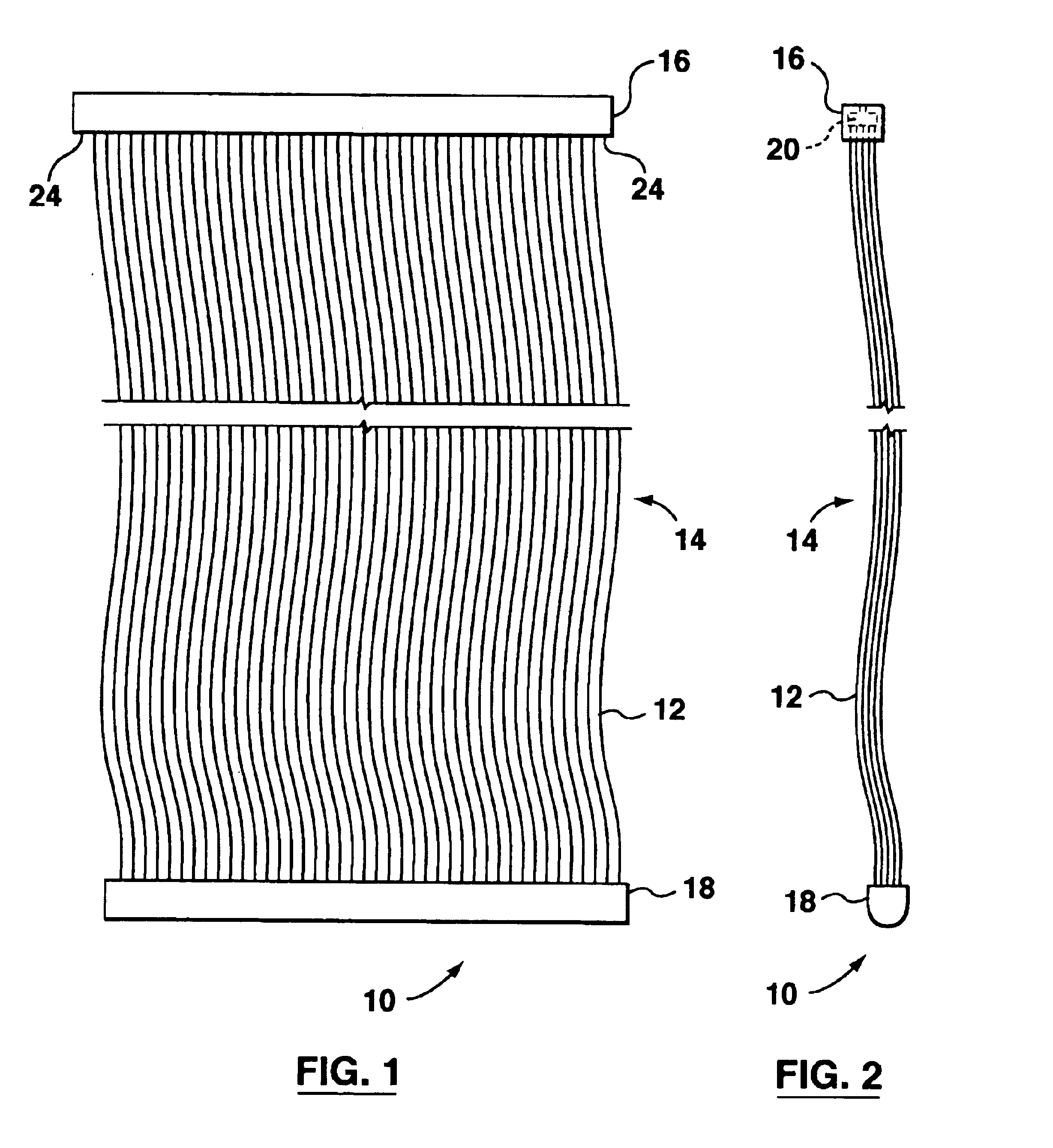
[0033]FIGS. 1 and 2 show simplified front and side elevations respectively of a filtering element 10. The element 10 has a plurality of hollow fibre membranes 12 in the form of a rectangular skein 14 suspended between an upper header 16 and a lower header 18. The rectangular skeins 14 may be between four and eight layers of membranes 12 deep (five layers being shown in FIG. 2), optionally up to 12 layers deep, and are in the range of several tens of membranes 12 wide. The element 10 itself does not include any permanently attached means for holding the headers 16, 18 in position relative to each other but the element 10 may be connected to a carrying frame if required for transport or handling. The lack of means for holding the headers 16...

second embodiment

A Second Embodiment

[0044]The following paragraphs describe a second embodiment, parts of which are shown in FIGS. 8 to 14. Although the description below may at times refer to specific figures, some components discussed may be shown only in others of FIGS. 8 to 14 or in figures discussed with other embodiments. The second embodiment is similar to the first embodiment in many respects. Aspects of the second embodiment that do not differ substantially from the first embodiment may not be described in the following paragraphs which will concentrate on the features of the second embodiment which differ from the first.

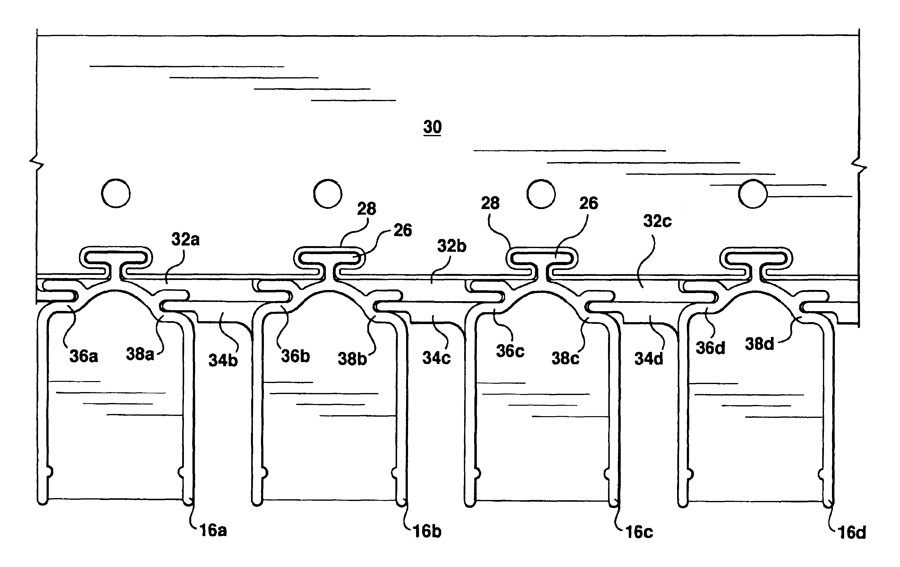
[0045]A second lower header 118 is shown in FIGS. 8A and 8B. A second upper header 116 (not shown in this figure) is similar, but mounted in an inverted position. The second lower header 118 has a second key 126 on its lower surface that may be continuous like that of the second header 18. Optionally, the second key 126 may be segmented, for example as shown in FIG. 8B, whi...

third embodiment

A Third Embodiment

[0051]The following paragraphs describe a third embodiment, parts of which are shown in FIGS. 15 to 18. Although the description below may at times refer to specific figures, some components discussed may be shown only in others of FIGS. 15 to 19 or in figures discussed with other embodiments. The third embodiment is similar to the first and second embodiments in many respects. Aspects of the third embodiment that do not differ substantially from the first or second embodiment may not be described in the following paragraphs which will concentrate on the features of the third embodiment which differ from the first or second.

[0052]FIGS. 15A and 15B show a third element 310. The third element 310 has a third lower header 318 and a third upper header 316 which are similar to the second lower header 118 and second upper header 116. However, the third headers 316, 318 differ, for example, in having third keys 326, third back caps 324 and third front caps 325 unlike rela...


PUM

PropertyMeasurementUnit
Massaaaaaaaaaa
Shapeaaaaaaaaaa
Permeation propertiesaaaaaaaaaa

Abstract

An apparatus for filtering a liquid in a tank has a plurality of elements and a frame for holding the elements while they are immersed in the liquid. The elements have a plurality of hollow fibre membranes attached to and suspended between an upper header and a lower header. The membranes are in fluid communication with one or more permeate channels in one or more of the headers. Releasable attachments between the headers and the frame allow the frame to releasably hold the elements by their headers. The size and configuration of the frame determines the positions of the upper and lower headers of each element relative to each other. Connections between the permeate channels and one or more permeate collection tubes attached to the frame are releasable and resealable connections which are made or broken automatically by the movements involved in inserting or removing an element into or out of the frame.

Description

[0001]This application is a continuation of U.S. application Ser. No. 10 / 146,934 filed May 17, 2002 which is (a) is a continuation in part of U.S. Pat. No. 09 / 889,352 filed Jul. 17, 2001, which is a National Stage entry of PCT / CA00 / 01359 filed Nov. 15, 2000 and (b) claims priority from Canadian application number CA 2,348,186, filed May 18, 2001. All of the patents and applications listed above, U.S. Pat. No. 09 / 848,012 and U.S. Pat. No. 60 / 201,725 are incorporated herein by this reference to them.FIELD OF THE INVENTION[0002]This invention relates to filtering membranes and particularly to modules of immersed, suction driven, ultrafiltration or microfiltration membranes used to filter water or wastewater.BACKGROUND OF THE INVENTION[0003]Submerged membranes are used to treat liquids containing solids to produce a filtered liquid lean in solids and an unfiltered retentate rich in solids. For example, submerged membranes are used to withdraw substantially clean water from wastewater an...

Claims


Application Information

Patent Timeline
IPC IPC(8): B01D61/18B01D63/04B01D63/02B01D65/08B01D61/20B01D65/00C02F1/44C02F1/74
CPCB01D61/18B01D63/02B01D63/024B01D63/026B01D63/043B01D63/046B01D65/08C02F1/444B01D61/20B01D2313/54B01D2315/06B01D2321/12B01D2321/185C02F1/74B01D2313/06B01D2313/21B01D2313/56B01D63/031
Inventor COTE, PIERRE LUCIENPEDERSEN, STEVEN KRISTIAN
Owner ZENON TECH PARTNERSHIP
Why Eureka
Try Eureka