Group wiring device for facilitating wire pair identification

a wire pair identification and group wiring technology, applied in the direction of coupling device connections, instruments, connection contact material, etc., can solve the problems of difficult to identify the wire pair, the conventional wire pair identification method is laborious and time-consuming, and the wiring system is concerned

Inactive Publication Date: 2005-05-31
YFC BONEAGLE ELECTRIC B V I L TD +1
View PDF4 Cites 31 Cited by
  • Summary
  • Abstract
  • Description
  • Claims
  • Application Information

AI Technical Summary

Benefits of technology

[0004]The primary object of the present invention is to provide a group wiring device which has built-in light emitting means and switch mechanism coupled with wire pair receptacle thereof. The switch mechanism is normally on a “CLOSE” status but can be switched to an “OPEN” status when a plug mates with the wire pair receptacle. When the switch mechanism is “CLOSE” and a testing voltage is applied to the circuit of the light emitting means, the light emitting means will emit light for assisting wire pair identification. After the process of wire pair identification is complete, the group wiring device is deemed to be in normal operation, that is, to perform ordinary signal transmitting functions. The wire pair receptacle will then be mated with plug of network cable so as to drive the switch mechanism to become “OPEN”. Therefore, the circuit of light emitting means becomes an open circuit and provides no function at all. As a result, the built-in light emitting means and switch mechanism of the present invention will not result in “loop back shorting” nor disrupt the communication at all.

Problems solved by technology

As a result, the wiring system is concerned.
It is obvious that management of the wires would be a critical issue for such a large wiring system.
It is obvious that such a conventional wire pair identification method is very laboring and time-wasting.
In a large wiring system, it may take days or even weeks to perform wire pair identification.
However, there are still deficiencies for the prior art method disclosed in U.S. Pat. No. 5,847,557.
Time waste still exists.
In addition, it is impossible for U.S. Pat. No. 5,847,557 to directly built-in the LEDs inside the jacks of the patch panel because the LED circuit will incur a short circuit between two contacts of the jack.
And, once the patch panel stack is under normal operation such as transmission of communication signals, the LED circuit will result in “loop back shorting” and seriously disrupt the communication.

Method used


Image

  • Group wiring device for facilitating wire pair identification
  • Group wiring device for facilitating wire pair identification
  • Group wiring device for facilitating wire pair identification

Examples


Embodiment Construction

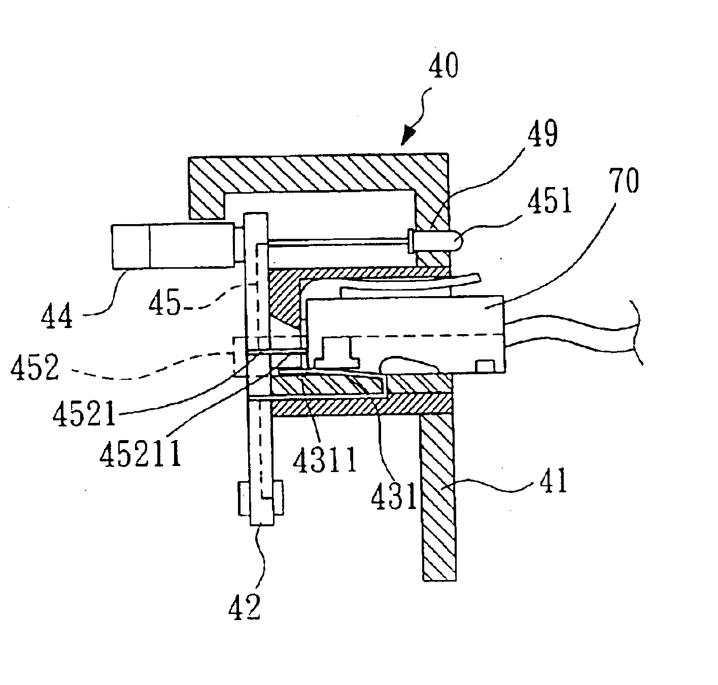
[0012]The primary object of the present invention is to provide a group wiring device which has built-in light emitting means and switch mechanism coupled with wire pair receptacle thereof. The switch mechanism is normally on a “CLOSE” status but can be switched to an “OPEN” status when a plug mates with the wire pair receptacle. When the switch mechanism is “CLOSE” and a testing voltage is applied to the circuit of the light emitting means, the light emitting means will emit light for assisting wire pair identification. After the process of wire pair identification is complete, the group wiring device is deemed to be in normal operation, that is, to perform ordinary signal transmitting functions. The wire pair receptacle will then be mated with plug of network cable so as to drive the switch mechanism to become “OPEN”. Therefore, the circuit of light emitting means becomes an open circuit and provides no function at all. As a result, the built-in light emitting means and switch mec...


PUM


Abstract

A group wiring device which has built-in light emitting means and switch mechanism coupled with wire pair receptacle thereof. The switch mechanism is normally on a “CLOSE” status but can be switched to an “OPEN” status when a plug mates with the wire pair receptacle. When the switch mechanism is “CLOSE” and a testing voltage is applied to the circuit of the light emitting means, the light emitting means will emit light for assisting wire pair identification. After the process of wire pair identification is complete, the group wiring device is deemed to be in normal operation, that is, to perform ordinary signal transmitting functions. The wire pair receptacle will then be mated with plug of network cable so as to drive the switch mechanism to become “OPEN”. Therefore, the circuit of light emitting means becomes an open circuit and provides no function at all. As a result, the built-in light emitting means and switch mechanism of the present invention will not result in “loop back shorting” nor disrupt the communication at all.

Description

1. FIELD OF THE INVENTION[0001]This invention relates to sorting electrical conductors, particularly to an improved group wiring device such like a patch panel which can be used with a voltage supplier for wire pair identification.2. BACKGROUND OF THE INVENTION[0002]It is often necessary to identify individual wires or circuits which extend between two locations. Please refer to FIG. 1. For example, a typical communication system such as internet service provider system, local area network (LAN) system, wide area network (WAN) system, metropolitan area network (MAN) system, intranet networking system, or telephone work center usually involves in hundreds or even thousands of end users located at different sites or places sharing the service (or controlled by) provided by the same server system 10. Some end users 11 may connect to the server system 10 from the internet 111 through a modern system 112. Some end users 12 may connect to the server system 10 via local servers 121 which m...

Claims


Application Information

Patent Timeline
Patent Type & Authority Patents(United States)
IPC IPC(8): H01R13/66H01R13/717G01R31/04H04Q1/14
CPCG01R31/041H04Q1/136H01R13/717H01R24/64H01R13/7175G01R31/67
Inventor HWANG, RICHARDHWANG, MEMIEEHWANG, WAYNEHWANG, JIM
Owner YFC BONEAGLE ELECTRIC B V I L TD
Why Eureka
Try Eureka