Multiple resolution helical imaging system and method

Inactive Publication Date: 2005-05-31
MARK ANDY
View PDF69 Cites 12 Cited by
  • Summary
  • Abstract
  • Description
  • Claims
  • Application Information

AI Technical Summary

Benefits of technology

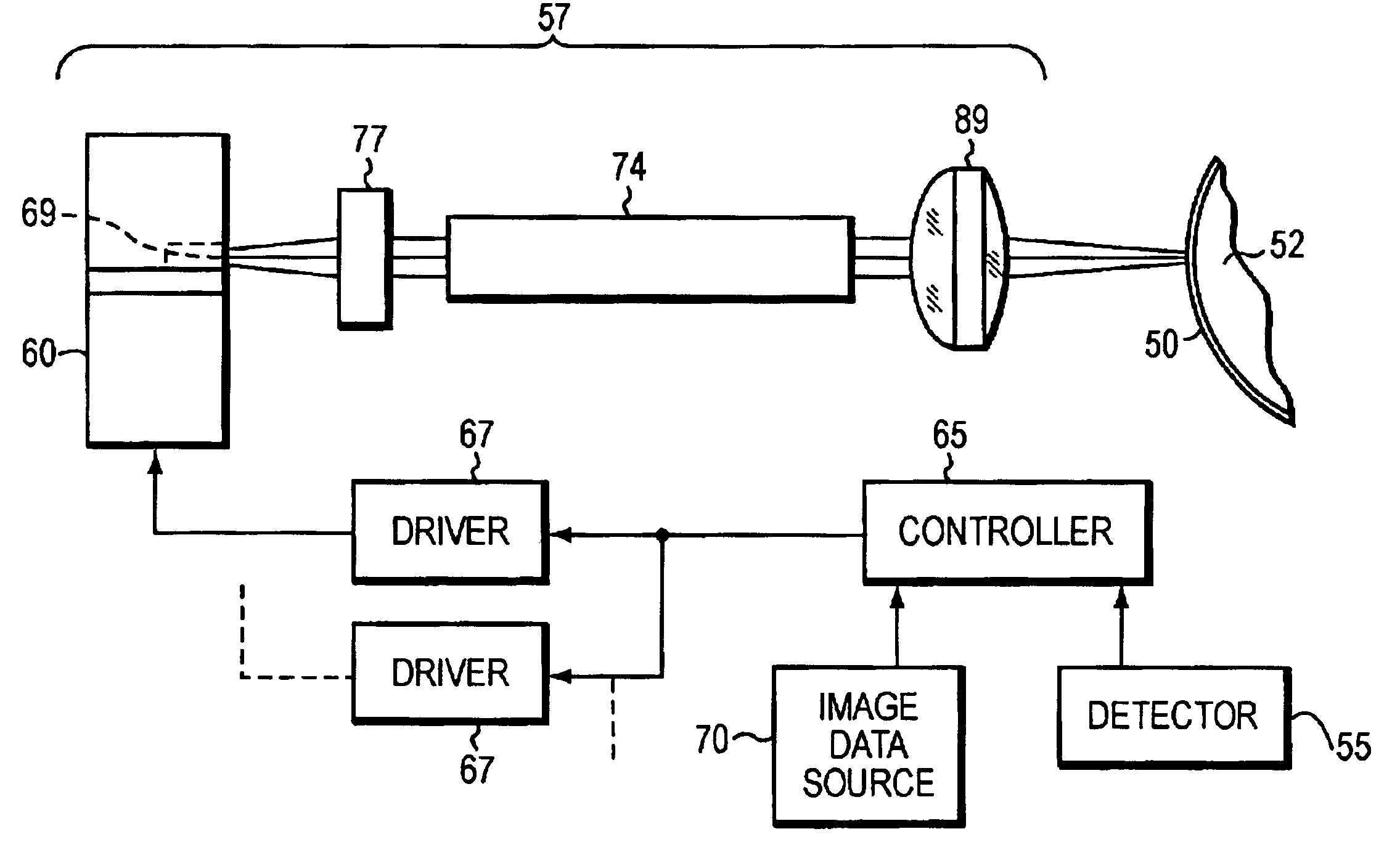
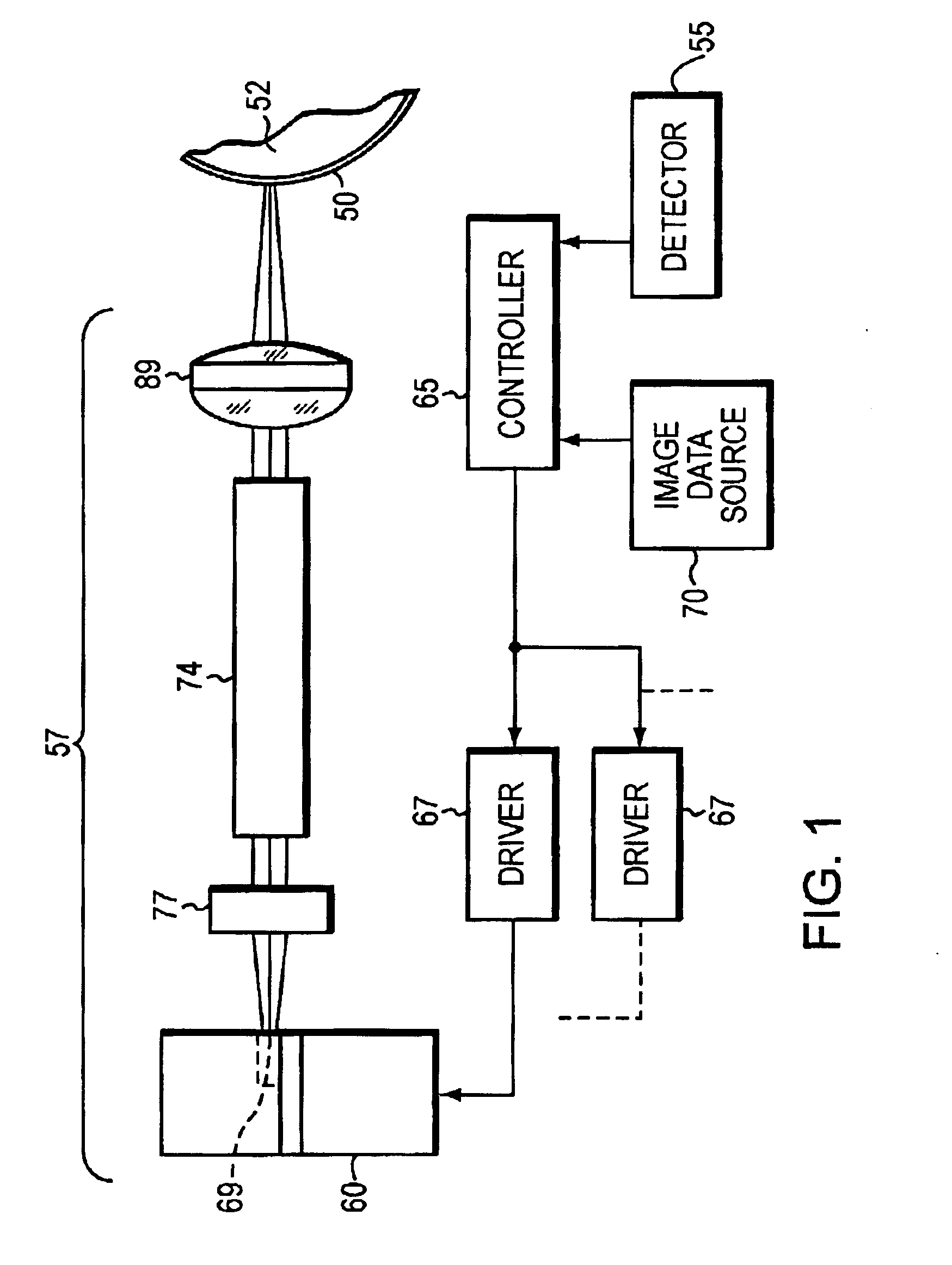
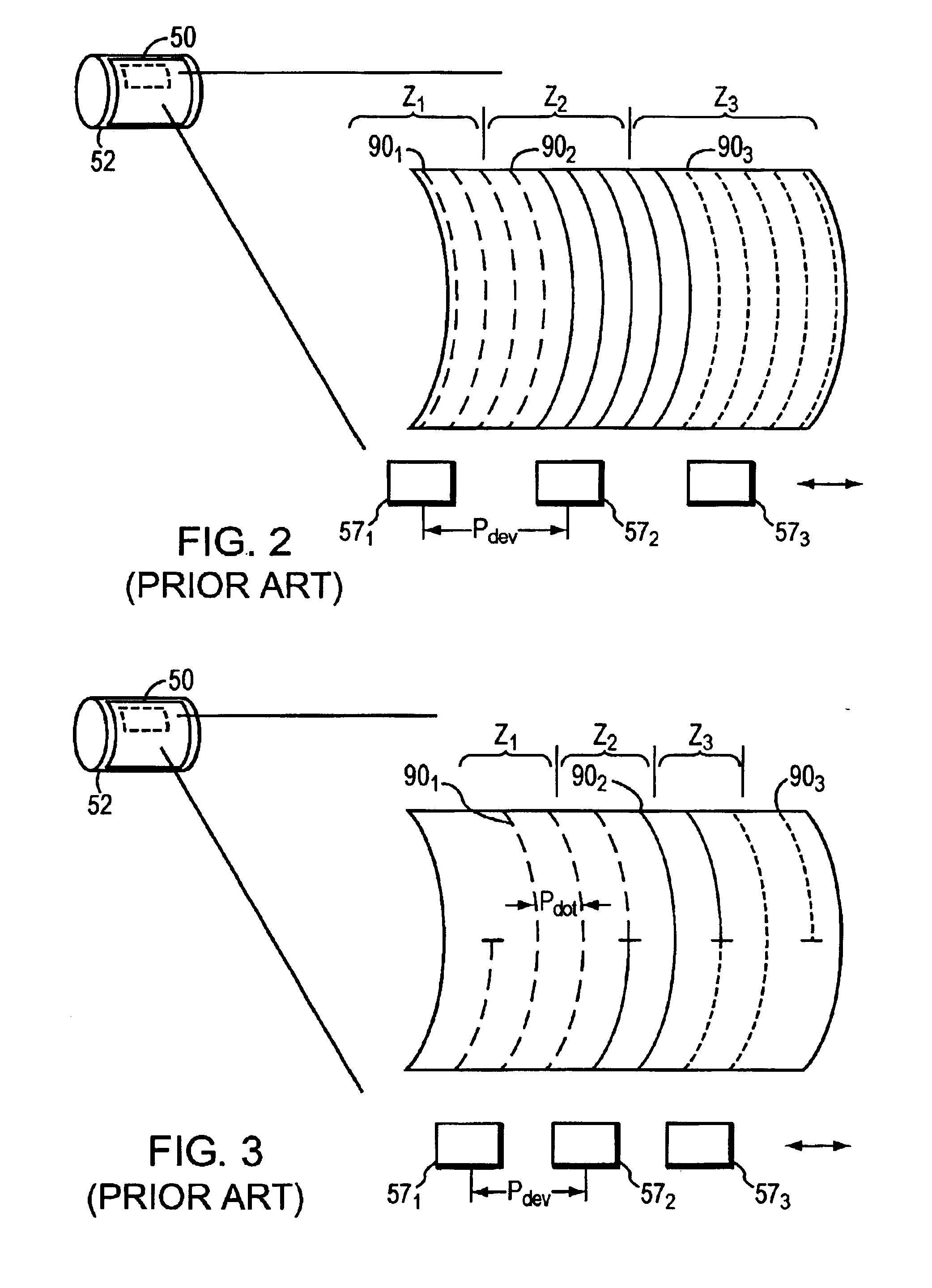
[0009]In accordance with this invention, the regions of the recording medium traversed by adjacent imaging devices are interlaced. By interlacing regions mixed by the different devices, differences in device imaging characteristics are aggregated and thereby rendered less noticeable. For example, susceptibility to periodic imaging artifact such as the Moire effect is reduced. The amount of axial distance traversed by a device during one cylinder rotation (the “helical step pitch”) is the device pitch or a fraction thereof rather than the much smaller dot pitch. As a result, each device traces a wide spiral across the cylinder. The space between turns imaged by t

Problems solved by technology

Unfortunately, because the zones are adjacent, this type of system produces visible a

Method used


Image

  • Multiple resolution helical imaging system and method
  • Multiple resolution helical imaging system and method
  • Multiple resolution helical imaging system and method

Examples


Example

[0026]Refer first to FIG. 1, which schematically illustrates the basic components of the environment to which the invention may be applied. A recording medium 50, such as a lithographic plate blank or other graphic-arts construction, is affixed to a support during the imaging process. In the depicted implementation, that support is a cylinder 52, around which recording medium 50 is wrapped. If desired, cylinder 52 may be straightforwardly incorporated into the design of a conventional lithographic press, serving as the plate cylinder of the press. Cylinder 52 is supported in a frame and rotated by a standard electric motor or other conventional means. The angular position of cylinder 52 is monitored by a shaft encoder associated with a detector 55. The optical components of the invention, organized as an array of imaging devices each containing the components indicated at 57, may be mounted in a writing head adapted for axial movement. In other embodiments, the optical components of...


PUM


Abstract

A multiple resolution imaging system employs an array of imaging devices each tracing a helical pattern on a recording medium. The imaging devices may be activated sequentially along multiple interlaced helical paths to allow a selectable image resolution with reduced imaging artifacts.

Description

RELATED APPLICATION[0001]This application claims the benefit of U.S. Provisional Application No. 60 / 358,077, filed Feb. 19, 2002, the entire disclosure of which is hereby incorporated by reference.BACKGROUND OF THE INVENTION[0002]1. Field of the Invention[0003]The present invention relates to digital imaging systems and methods, and more particularly to digital imaging systems that apply image information along helical paths.[0004]2. Description of the Related Art[0005]In many digital graphic-arts applications, recording media are imaged by arrays of imaging devices. For example, to circumvent the cumbersome photographic development, plate-mounting and plate-registration operations that typify traditional printing technologies, practitioners have developed electronic alternatives that store the imagewise pattern in digital form and impress the pattern directly onto the plate or recording medium. Plate-imaging devices amenable to computer control include various forms of lasers. For ...

Claims


Application Information

Patent Timeline
IPC IPC(8): H04N1/06H04N1/191
CPCH04N1/0414H04N1/0443H04N1/1915H04N1/0678H04N1/06H04N1/1912
Inventor WILLIAMS, RICHARD A.WOOD, CRAIG
Owner MARK ANDY
Why Eureka
Try Eureka