Scaling bar

a scaling bar and bar body technology, applied in the field of scaling bars, can solve the problems of relatively inefficient known scaling tools

Inactive Publication Date: 2005-06-07
ATELIER DUSINAGE LAQUERRE & FILS
View PDF12 Cites 10 Cited by
  • Summary
  • Abstract
  • Description
  • Claims
  • Application Information

AI Technical Summary

Benefits of technology

[0017]second cam means, co-operating with said handle and with said first cam means for providing coarse-grade leverage force to furthe...

Problems solved by technology

However, these known scaling to...

Method used


Image

  • Scaling bar
  • Scaling bar
  • Scaling bar

Examples


Embodiment Construction

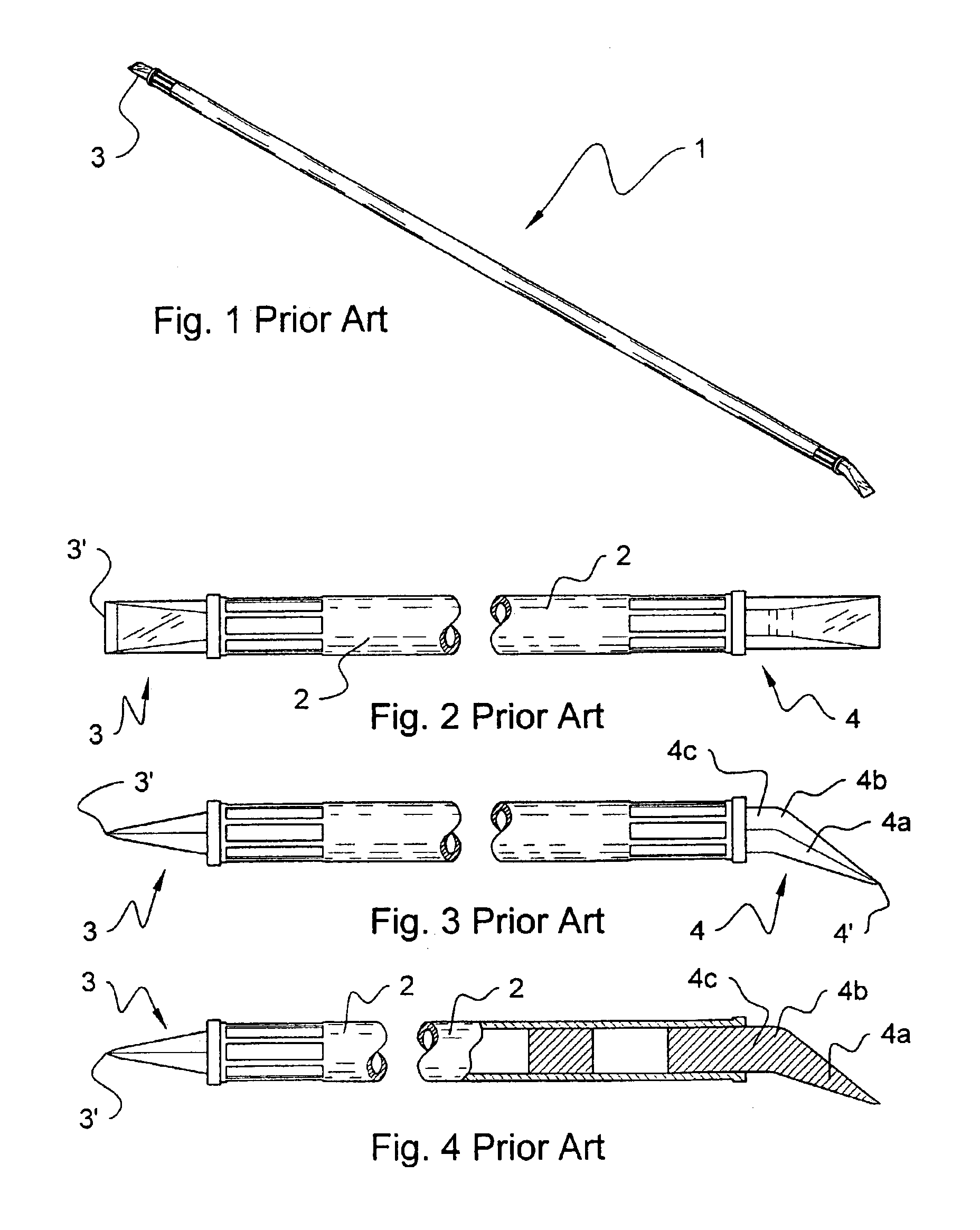
[0035]FIGS. 1 to 4 show a scaling bar 1 according to prior art. Scaling bar 1 comprises two pick ends 3 and 4 installed on opposite ends of a shaft 2. Pick end 3 is V-shaped and defines a leading edge 3′. Pick end 4 comprises a V-shaped tip portion 4a defining a leading edge 4′, an elbow 4b, and a straight end portion 4c.

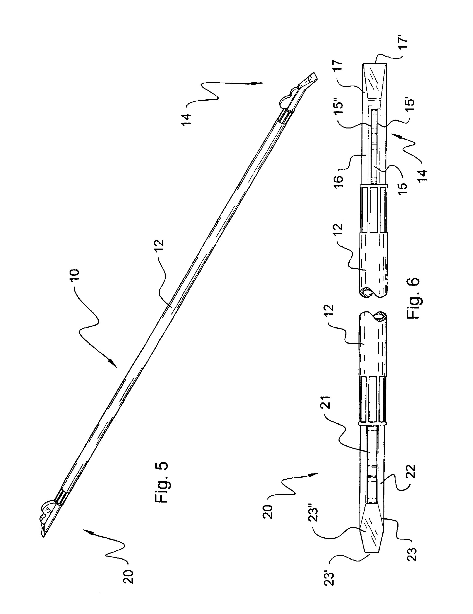
[0036]With further reference to FIG. 5, a scaling bar 10 is illustrated according to a first embodiment of the present invention. Scaling bar 10 is used for dislodging hazardous loose rocks clung on to wall structures of mine shafts, which, if not removed, can unexpectedly fall on miners or other workmen, hence causing serious bodily injuries.

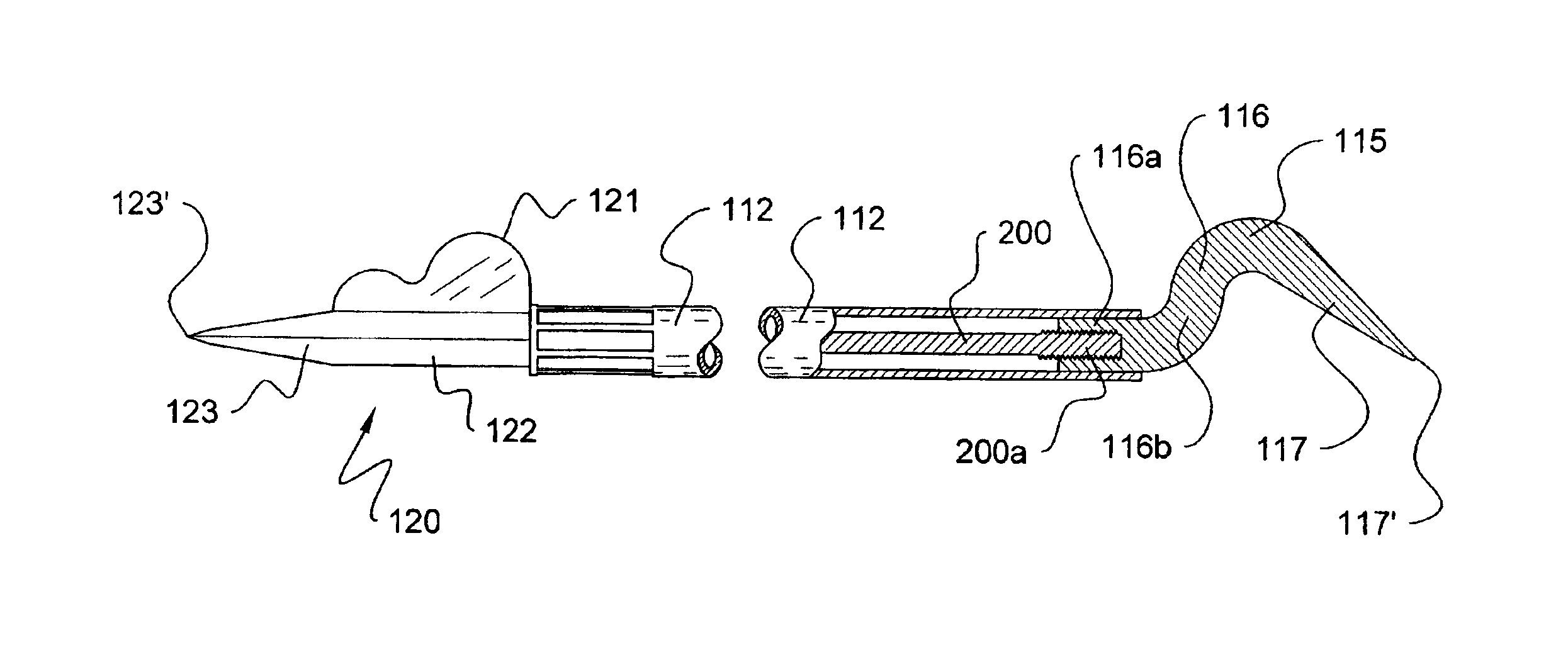
[0037]Scaling bar 10 comprises an elongated shaft 12 having a pick member 14 firmly attached coaxially to one end thereof, and a pick member 20 fixedly attached coaxially to the other end thereof.

[0038]Shaft 12 can be for example an aluminum hollow tube having a circular or polygonal (e.g. quadrangular) cross-section, and can ...


PUM


Abstract

A scaling bar for prying overhanging rocks from rocky wall structures. The scaling bar comprises an elongated tubular shaft and a first pick member attached to one end thereof, and, optionally, a second pick member attached to a second end thereof. At least one of the two pick members comprises an end portion closely fitted into engagement with the tubular shaft, a tip portion defining a substantially sharp leading edge for easier penetration in the rocky structure, and a cam element. The cam element comprises a first and a second leverage bulges, whereby by displacing the shaft, a lever is formed for dislodging unstable overhanging rocks with minimized physical effort from the workman. The second inner leverage bulge provides greater leverage to the tip portion than the first leverage bulge, but the size of the first leverage bulge is smaller, and can hence engage narrower clefts than the second leverage bulge. In use, a workman axially inserts the pick member of the scaling bar in a cleft adjacent to an unstable overhanging rock, and applies a transverse load by prying the unstable rock using the leverage provided by the first leverage bulge, hence widening the cleft. Subsequently, if necessary, the pick member is further axially driven into the cleft, and the workman again applies a transverse load to pry the rock away again using the leverage provided by the second leverage bulge. This procedure can be repeated so as to sink further into the rock bed, until the rock has been dislodged from its bed.

Description

[0001]This patent application claims priority of co-pending U.S. Provisional patent application No. 60 / 399,252 filed on Jul. 19, 2002FIELD OF THE INVENTION[0002]The invention is in the field of scaling bars for use by miners and other workmen to pry loose rocks or other materials from the side wall or roof of a tunnel, mine shafts, or the like.BACKGROUND OF THE INVENTION[0003]In galleries of subterranean mines, it often occurs that overhanging loose rocks appear on wall surfaces, for example after the dynamiting of a mine shafts. It is essential to regularly remove these unstable rocks, as a safety precaution against injuries to mine workers.[0004]It is known to use scaling bars for this purpose. Such scaling bars are elongated rigid tools comprising a penetrating pick tip at one end thereof, for insertion between unstable rocks. An elbowed section of the rigid tool forms a lever, for enabling a mine worker to dislodge these rocks with reduced physical effort. More particularly, the...

Claims


Application Information

Patent Timeline
IPC IPC(8): E21C37/22E21C37/00B66F15/00E21C37/02E21C37/26
CPCE21C37/22B66F15/00
Inventor BRUNEAU, MARCELLIN
Owner ATELIER DUSINAGE LAQUERRE & FILS
Why Eureka
Try Eureka